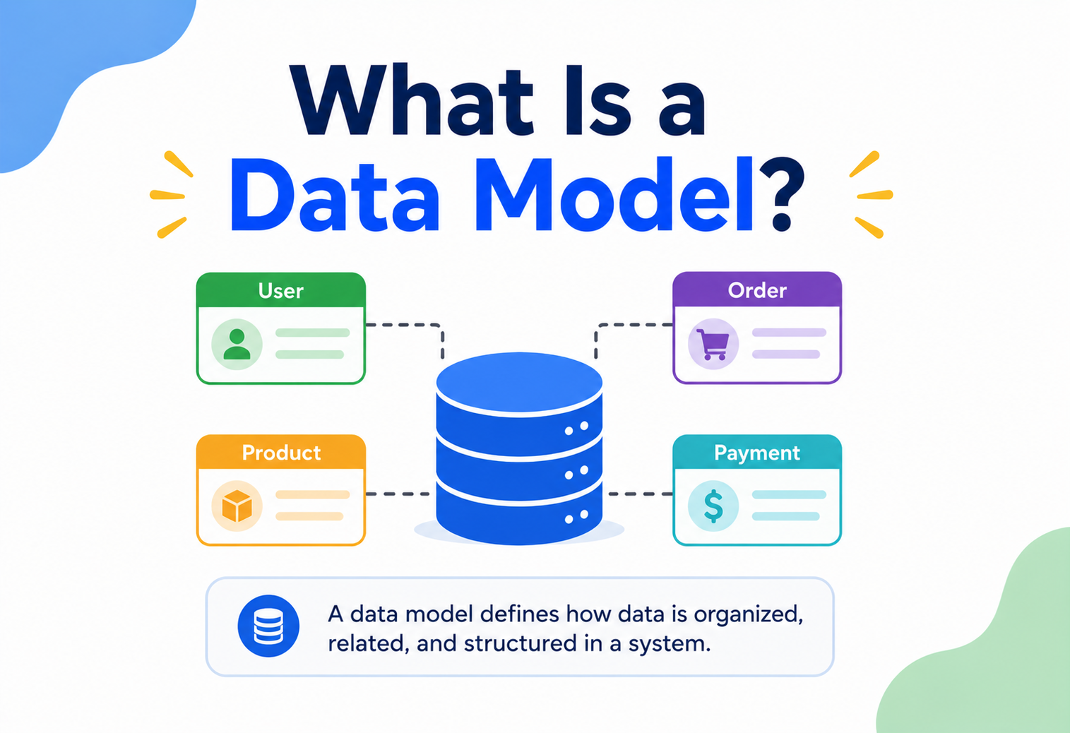
What Is a Data Model?
From a napkin sketch to a Netflix‑scale database — a complete, beginner‑friendly walkthrough of how software decides what data looks like, how it’s organised, and how it’s used, with diagrams, Java examples, and real production practices.
Introduction & History
Why every real system starts with a data model — from 1960s hierarchical files to today’s cloud‑native polyglot stores.
Imagine you are building a giant toy‑box organiser. Before you buy a single container, you first decide: which toys go together? Do the small cars need their own tray? Should the building blocks be sorted by colour or by size? You are not touching a single toy yet — you are just deciding the plan for how everything will be organised. That plan, drawn on paper before anything is built, is exactly what a data model is for computer systems.
A data model is a way of organising and describing data so that both humans and computers can understand what the data means, how pieces of data relate to each other, and what rules the data must follow. It is the blueprint of information — drawn before a single line of database code is written, and referred to constantly afterward whenever anyone builds a feature, writes a report, or debugs a problem.
A data model is like the architectural blueprint of a house. The blueprint does not contain any bricks, paint, or furniture — but it precisely defines where each room is, how big it is, and how rooms connect through doors and hallways. A builder (the database) later uses that blueprint to construct the real house (the actual stored data).
The idea of formally modelling data is older than most people expect. In the 1960s, early computer systems stored data in whatever format a specific program needed, which meant every application had its own private, tangled way of reading and writing files. If two programs needed the same customer information, they often duplicated it in incompatible formats. This created enormous pain: change one field, and a dozen programs would silently break.
In 1970, a researcher at IBM named Edgar F. Codd published a paper proposing the relational model — the idea that data could be represented as simple tables (rows and columns) with a strong mathematical foundation, independent of how it was physically stored on disk. This was revolutionary because, for the first time, the logical shape of data was separated from the physical way it was stored. Codd’s work eventually led to SQL and to relational database systems like Oracle, IBM Db2, PostgreSQL, and MySQL — technologies still powering the majority of the world’s applications today.
Later, as the internet grew and applications needed to handle massive scale, flexible schemas, and rapidly changing requirements, new data modelling styles emerged: document models (MongoDB), key‑value models (Redis, DynamoDB), wide‑column models (Cassandra, HBase), and graph models (Neo4j). Each of these represents a different philosophy of “what is the best shape for this data?” — and understanding data models is what lets an engineer choose correctly among them.
It helps to think of data modelling as sitting at the intersection of three different skills. It borrows precision from mathematics (sets, relations, and constraints), storytelling from communication (explaining what a “Customer” or an “Order” actually means to people who aren’t engineers), and pragmatism from engineering (accepting that no model is perfect, only “good enough” for the problem at hand, today, with room to grow tomorrow). A software engineer who is comfortable with all three skills tends to design systems that age gracefully, rather than needing painful rewrites every time the business changes direction.
A short history
Hierarchical & network models
Early systems like IBM’s IMS organised data as trees or networks, tightly coupled to physical storage and application code.
The relational model
Edgar Codd introduces tables, rows, and mathematical set theory, decoupling logical structure from physical storage.
SQL & commercial RDBMS
SQL becomes the standard query language; Oracle, DB2, and Sybase bring relational modelling to enterprises.
Object‑oriented modelling
UML and object databases attempt to model data as objects with behaviour, matching object‑oriented programming languages.
The NoSQL movement
Web‑scale companies (Google, Amazon, Facebook) build document, key‑value, column, and graph models for flexibility and horizontal scale.
Polyglot & cloud‑native modelling
Modern systems mix multiple data models per application (polyglot persistence), driven by microservices and cloud‑managed databases.
Problem & Motivation
Why do we need data models at all? Why not just let each programmer store data however feels convenient in the moment? Let’s walk through what happens without one.
Imagine three different developers building parts of the same online store. One stores a customer’s name as a single field called fullName. Another splits it into first_name and last_name. A third stores it as an object with a given and family key. Now imagine the marketing team asks, “Send me a report of all customer names.” Which format is correct? Nobody agrees, because nobody defined a shared blueprint first.
Without a data model, every part of a system invents its own private understanding of what data means. This leads to duplicated data, contradictory formats, silent bugs, wasted storage, and features that break the moment two teams’ assumptions collide.
A data model solves this by acting as a single source of truth about the shape and meaning of data. It answers questions like:
- What “things” (entities) does our system need to remember? (Customers, Orders, Products…)
- What details (attributes) does each thing have? (A Customer has a name, email, phone…)
- How do these things relate to each other? (A Customer places many Orders)
- What rules must always be true? (An Order must always belong to exactly one Customer)
- What data type and format is each detail stored in? (Email is text, Price is a decimal number)
Think of a school’s student record system. If the front office, the library, and the sports department each kept separate, differently‑formatted lists of student names and IDs, a single spelling mistake could mean a student’s library fines don’t match their actual identity. A shared “Student ID card” format used everywhere solves this — that shared format is a data model.
Beginner example
Suppose you are building a simple to‑do list app. Before writing any code, you might sketch:
Task
 - id (unique number)
 - title (text)
 - isDone (true/false)
 - dueDate (date)
 - ownerId (links to a User)

User
 - id (unique number)
 - name (text)
 - email (text)
This tiny sketch is already a data model. It defines two entities (Task, User), their attributes, and a relationship (a Task belongs to a User via ownerId).
Software example
In an e‑commerce system, the data model defines that a Product has a price and stock count, an Order references one or more Products with quantities, and a Customer places Orders. Every checkout button, invoice PDF, and inventory alert in the app depends on this shared understanding staying consistent.
Production example
Amazon sells hundreds of millions of distinct products across categories as different as books, groceries, and electronics. Their product data model must be flexible enough to hold a book’s “author” and a laptop’s “RAM size” without turning into chaos — a problem solved through carefully designed, category‑specific attribute schemas layered on top of a common core product model.
Core Concepts
Let’s build up the vocabulary of data modelling one term at a time. Each term is a building block for the next, so read them in order the first time.
Entity
What it is: An entity is a distinct “thing” or concept that your system needs to store information about — a person, place, object, or event. Why it exists: Software needs to talk about real‑world (or business) concepts in a structured way. Grouping related data under a named entity keeps things organised. Where it’s used: Almost every system: Customer, Product, Order, Employee, Flight, Message.
An entity is like a labelled folder in a filing cabinet — “Customers,” “Orders,” “Products” — each folder holds related paperwork.
Example: In a library system, Book, Member, and Loan are entities.
Attribute (field / column)
What it is: A single piece of information that describes an entity. Why it exists: An entity alone (like “Book”) is meaningless without details — a title, an author, a price.
If the entity is a folder, an attribute is one labelled sticky note inside it: “Title: Harry Potter,” “Author: J.K. Rowling.”
Example: A Book entity might have attributes: isbn, title, author, publishedYear, price.
Relationship
What it is: A meaningful connection between two (or more) entities. Why it exists: Real‑world things are connected — a Customer places an Order, a Student enrolls in a Course. Relationships let the model capture these connections.
A relationship is like a piece of string tied between two folders, showing they are linked — “this Order folder belongs to that Customer folder.”
Types of relationships:
| Type | Meaning | Example |
|---|---|---|
| One‑to‑One (1:1) | One record in A relates to exactly one in B | A Person has one Passport |
| One‑to‑Many (1:N) | One record in A relates to many in B | One Customer places many Orders |
| Many‑to‑Many (M:N) | Many records in A relate to many in B | Students enroll in many Courses; Courses have many Students |
Key (primary key & foreign key)
What it is: A primary key uniquely identifies each record in an entity. A foreign key is an attribute in one entity that points to the primary key of another, implementing a relationship.
A primary key is like a student’s unique roll number — no two students share it. A foreign key is like writing that roll number on a library card to show exactly who borrowed a book.
Example: Order.customerId is a foreign key pointing to Customer.id (the primary key of Customer).
Schema
What it is: A schema is the complete, formal definition of entities, attributes, relationships, and constraints for a database — essentially the data model written down in a form the database can enforce.
If the data model is the blueprint, the schema is the signed, official building permit that the city (the database engine) will enforce.
Constraint
What it is: A rule the data must obey, such as “email must be unique” or “age cannot be negative.”
A constraint is like a rule at a swimming pool: “no running,” enforced by a lifeguard (the database engine) at all times.
Normalization
What it is: A process of organising data to reduce duplication by splitting it into smaller, related tables. Why it exists: Storing the same information twice (like a customer’s address in every one of their orders) wastes space and risks inconsistency if only one copy gets updated.
Instead of writing your home address on every single letter inside a filing folder, you write it once on a “profile card” and every letter just references that card.
Cardinality
What it is: The number of instances of one entity that can be associated with instances of another entity (this is really the precise version of the 1:1 / 1:N / M:N relationship types above).
Domain vs. data type
What it is: A domain is the set of allowed values for an attribute — for example, the domain of “day of week” is only the seven named days, not any arbitrary text. A data type (integer, string, date, boolean) is the technical container used to hold a value; a domain is the business meaning layered on top of it.
A data type is like the shape of a container — a jar can technically hold candy, screws, or coins. The domain is the label on the jar that says “only red candy goes here.” Two jars can be the same shape (data type) but hold completely different allowed contents (domain).
Example: An attribute called rating might use the integer data type, but its domain is restricted to the numbers 1 through 5 — enforced through a CHECK constraint or an application‑level validation rule.
Degree and cardinality of a relationship
Two words are often confused: degree refers to how many entities participate in a relationship (most relationships are “binary,” connecting exactly two entities, though “ternary” relationships connecting three do exist). Cardinality refers to how many instances of each entity can participate — the “one” or “many” you saw in the table above. Getting cardinality wrong is one of the most common real‑world modelling mistakes, because it is very easy to assume a relationship is one‑to‑many when, in reality, business rules eventually require many‑to‑many. For example, a team might assume a Product belongs to only one Category, until the business later decides a Product can belong to several Categories at once — forcing a costly redesign.
Weak entities and identifying relationships
What it is: A weak entity is one that cannot be uniquely identified by its own attributes alone — it depends on a related “owner” entity for identity.
Think of a hotel room number. “Room 204” is meaningless on its own — there could be a “Room 204” in dozens of different hotels. The room only becomes uniquely identifiable when combined with the hotel it belongs to.
Example: An OrderLine (a single line item on an order, like “2x Blue T‑Shirt”) often only makes sense combined with its parent Order — its identity is orderId + lineNumber, not a standalone ID.
If you can explain your data model out loud in plain sentences — “A Customer places many Orders. Each Order contains many Products. Each Product has a price.” — you already understand the core of data modelling. Diagrams and code just formalise those sentences.
Architecture & Components: The Three‑Schema Approach
Professional data modelling is not done in a single step. It happens in three progressively detailed stages, often called the three‑schema architecture (originally proposed by the ANSI/SPARC standards committee in the 1970s).
This separation is one of the most important ideas in all of database engineering, because it lets the business meaning of data stay stable even while the technology underneath changes.
1. Conceptual data model
What it is: A high‑level, technology‑free view of what entities exist and how they relate — aimed at business stakeholders, not engineers. Where it’s used: Early planning meetings, requirement discussions with non‑technical stakeholders.
This is like a rough sketch of a house on a napkin — “there’s a kitchen, two bedrooms, and a garage” — with no measurements or wiring diagrams yet.
2. Logical data model
What it is: A more detailed model that defines attributes, data types (in a general sense), keys, and relationships — but still independent of any specific database product. Where it’s used: Design reviews between architects and developers, before deciding on Postgres vs. MongoDB vs. Cassandra.
This is the detailed architectural blueprint with room measurements and door placements — but it does not yet specify whether the walls will be brick or wood.
3. Physical data model
What it is: The actual implementation‑ready design: specific table names, exact column data types, indexes, partitioning strategy, and storage engine details for one specific database technology. Where it’s used: Right before writing the actual CREATE TABLE statements or defining NoSQL collections.
This is the final construction plan handed to the builders, specifying exact brick types, pipe diameters, and electrical wire gauges.
Why bother with three separate levels instead of jumping straight to tables? Because each level protects against a different kind of change. If the business adds a new rule, you update the conceptual model. If you switch database vendors, you rebuild only the physical model — the conceptual and logical models, and everyone’s shared understanding of the business, stay untouched. This is called data independence, and it’s one of Codd’s original, foundational insights.
Entity‑Relationship Diagram (ERD)
The most common way to visualise a conceptual or logical data model is an Entity‑Relationship Diagram (ERD). Boxes represent entities, lines represent relationships, and symbols on the lines show cardinality.
Notice the symbols: ||--o{ means “exactly one on this side, zero‑or‑many on the other side.” These crow’s‑foot notations are a standard visual language that any trained engineer can read, regardless of which company or country they work in — much like how music notation is understood by musicians everywhere.
Internal Working: From Model to Running Code
How does a nicely drawn diagram turn into something a program can actually use? Let’s trace the journey.
Step 1: The model becomes a schema
The logical/physical data model is translated into a schema definition understood by the database engine — for relational databases this is SQL’s CREATE TABLE statements; for document databases it may be a JSON Schema or simply convention‑based (schema‑less, validated in application code).
CREATE TABLE customer (
    id BIGINT PRIMARY KEY AUTO_INCREMENT,
    name VARCHAR(120) NOT NULL,
    email VARCHAR(160) UNIQUE NOT NULL
);

CREATE TABLE orders (
    id BIGINT PRIMARY KEY AUTO_INCREMENT,
    customer_id BIGINT NOT NULL,
    order_date DATE NOT NULL,
    FOREIGN KEY (customer_id) REFERENCES customer(id)
);
Step 2: The schema becomes an application model (ORM)
Application developers rarely write raw SQL for every operation. Instead, they use an Object‑Relational Mapper (ORM) — a library that maps database tables to programming‑language classes/objects. In Java, the most common ORM is Hibernate, implementing the JPA (Jakarta Persistence API) standard.
An ORM is like a translator standing between two people who speak different languages — your Java code speaks “objects,” the database speaks “tables and rows,” and the ORM translates seamlessly in both directions.
import jakarta.persistence.*;

@Entity
@Table(name = "customer")
public class Customer {

    @Id
    @GeneratedValue(strategy = GenerationType.IDENTITY)
    private Long id;

    @Column(nullable = false, length = 120)
    private String name;

    @Column(nullable = false, unique = true, length = 160)
    private String email;

    @OneToMany(mappedBy = "customer", cascade = CascadeType.ALL)
    private List<Order> orders = new ArrayList<>();

    // Constructors, getters, and setters omitted for brevity
}

@Entity
@Table(name = "orders")
public class Order {

    @Id
    @GeneratedValue(strategy = GenerationType.IDENTITY)
    private Long id;

    @ManyToOne
    @JoinColumn(name = "customer_id", nullable = false)
    private Customer customer;

    @Column(name = "order_date", nullable = false)
    private LocalDate orderDate;

    // Constructors, getters, and setters omitted for brevity
}
Here, the @Entity, @Column, and @OneToMany/@ManyToOne annotations directly express the same entities, attributes, and relationships defined earlier in the ERD — just written in a form the Java compiler and Hibernate understand. This is a beautiful example of how a data model flows unbroken from a whiteboard sketch all the way into working code.
Step 3: The engine enforces and stores
When your Java code calls save() on a Customer object, Hibernate translates it into an INSERT SQL statement. The database engine then checks all constraints (uniqueness, foreign keys, not‑null rules) before writing bytes to disk, typically inside a B‑Tree index structure for fast lookups later.
Even in schema‑less (NoSQL) databases, a data model still exists — it just lives in application code and documentation instead of being enforced by the database engine itself. “Schema‑less” does not mean “model‑less”; it means the enforcement responsibility moved.
Validation: the model’s first line of defence
Before any data even reaches the ORM, most well‑built systems run it through a validation layer that checks the incoming data against the rules defined by the model — is the email formatted correctly, is the age a positive number, is a required field actually present? In Java, this is commonly done using Bean Validation (JSR 380) annotations directly on the model classes, keeping the validation rules physically next to the fields they protect:
public class CustomerRequestDTO {

    @NotBlank(message = "Name is required")
    @Size(max = 120)
    private String name;

    @Email(message = "Email must be valid")
    @NotBlank
    private String email;
}
This layered approach — validate in the application, then enforce again in the database — means that even if a bug slips past the first check, the database itself acts as a final, trustworthy safety net.
Data Flow & Lifecycle
A data model is not a one‑time artefact drawn at the start of a project and forgotten. It has a lifecycle that mirrors the life of the software itself.
Requirements gathering
Business analysts and engineers interview stakeholders to identify entities and rules (“we need to track customers, orders, and refunds”).
Conceptual design
A high‑level ERD is drawn, reviewed, and agreed upon by both business and technical stakeholders.
Logical design
Attributes, data types, and normalisation decisions are added; the model is technology‑agnostic but detailed.
Physical design
A specific database technology is chosen; tables, indexes, partitions, and constraints are finalised.
Implementation
Schema migration scripts run; ORM entity classes are written; the database goes live.
Evolution
New features require schema changes — adding columns, splitting tables, adding indexes — managed through versioned migrations.
Deprecation / archival
Old fields or entire entities are phased out, historical data is archived or deleted according to retention policy.
This lifecycle repeats continuously; mature engineering teams treat schema changes with the same rigour as code changes — reviewed, versioned, and tested, using tools like Flyway or Liquibase for relational databases.
Runtime data flow
Beyond the design lifecycle, it helps to see how a single piece of data flows through a modelled system at runtime — from user input to storage and back out again.
Advantages, Disadvantages & Trade‑offs
Investing in a well‑designed data model is not free — it takes time and discipline. Understanding the trade‑offs helps you decide how much rigour a given project needs.
Advantages
- Prevents duplicate and inconsistent data
- Makes communication between teams precise and unambiguous
- Enables the database to enforce correctness automatically
- Speeds up onboarding — new engineers read the model, not tribal knowledge
- Provides a stable foundation for scaling and future features
- Improves query performance through proper indexing decisions made early
Disadvantages & trade‑offs
- Upfront design takes time before any visible feature ships
- Over‑normalising can hurt read performance (too many joins)
- Rigid schemas can slow down fast‑changing startups
- Poorly chosen models are expensive to fix once data has accumulated
- Requires ongoing governance as the system grows (migrations, reviews)
Normalization vs. denormalization
One of the most common trade‑off decisions is how “normalised” to make a model.
| Aspect | Normalised | Denormalised |
|---|---|---|
| Data duplication | Minimal | Higher (data repeated for speed) |
| Write consistency | Easy (single source of truth) | Harder (must update copies) |
| Read performance | May need many joins | Often faster (fewer joins) |
| Best for | Transactional systems (OLTP) | Analytics/reporting (OLAP), caching layers |
Performance & Scalability
How you model data has a direct, often dramatic, effect on how fast and how big your system can grow.
Indexing
What it is: A data structure (commonly a B‑Tree or hash index) that lets the database find rows quickly without scanning the entire table.
An index is like the index page at the back of a textbook — instead of reading every page to find “photosynthesis,” you jump straight to page 214.
Your data model determines which columns need indexes — typically primary keys, foreign keys, and columns frequently used in WHERE clauses.
Partitioning & sharding
What it is: Splitting one large logical dataset across multiple physical storage units (partitions within one database, or shards across many database servers) so no single machine becomes a bottleneck.
Instead of one giant filing cabinet holding every customer file in the country, you have one cabinet per state — each smaller, faster to search, and manageable independently.
A good data model chooses a sensible partition key (like customerRegion or userId) so related data lands together, minimising expensive cross‑partition queries.
Query patterns drive the model (NoSQL philosophy)
In relational modelling, you typically normalise first and optimise queries later. In NoSQL databases like DynamoDB or Cassandra, the philosophy flips: you design your data model around your known access patterns first (“we always fetch a user’s last 10 orders together”) and accept some duplication to make those specific queries extremely fast.
Adding an index on every column “just in case.” Every index speeds up reads but slows down writes (since the index must also be updated), and consumes extra storage. Index only what your real query patterns need.
Connection pooling and the model’s access frequency
Performance is not only about the shape of stored data — it’s also about how often and how heavily the model gets hit. Entities that are read on nearly every request (like a logged‑in User record) are prime candidates for caching and connection pooling optimisations, while rarely accessed entities (like a yearly TaxReport) can safely live on cheaper, slower storage tiers. Recognising these “hot” and “cold” parts of the model early lets architects plan tiered storage strategies (e.g., hot data in SSD‑backed databases, cold data in object storage like Amazon S3 Glacier) well before performance problems appear in production.
Denormalization for read‑heavy workloads
Some production systems intentionally maintain a “read‑optimised” copy of the data model alongside the normalised “write‑optimised” copy. This pattern, sometimes called Command Query Responsibility Segregation (CQRS), separates the model used for writing data (typically normalised, consistency‑focused) from the model used for reading data (typically denormalised, flattened, and tuned for the exact queries a UI needs). It adds complexity — two models must be kept in sync, usually through asynchronous events — but it can dramatically improve both read and write performance in high‑traffic systems.
High Availability & Reliability
A data model also influences how resilient a system is to failures — because how data is structured affects how it can be replicated and recovered.
Replication
What it is: Keeping copies of the same data on multiple servers so that if one fails, another can serve requests without data loss.
Like keeping duplicate copies of an important document in two different safes, in two different buildings — if a fire destroys one, the other survives.
Models with clear ownership boundaries (e.g., “all of a customer’s data belongs together”) make replication and failover cleaner, because related data can be replicated and recovered as one consistent unit.
The CAP theorem
Distributed systems face a fundamental trade‑off described by the CAP theorem: when a network partition (communication failure between servers) happens, a system can guarantee either full Consistency (every read sees the latest write) or full Availability (every request gets a response), but not both at the same time.
This directly affects data modelling: a banking ledger entity almost always needs strong consistency (you cannot show two different balances to two different tellers), while a “likes count” on a social media post can tolerate brief inconsistency (eventual consistency) in exchange for higher availability and speed.
Backup & disaster recovery
A well‑modelled schema, with clear entity boundaries and relationships, makes point‑in‑time backups and restores far more predictable — you know exactly which tables/collections must be restored together to keep referential integrity intact.
Security
Data modelling decisions have direct security consequences — deciding what data exists and how it’s structured is the first line of defence.
Sensitive data classification
A good data model explicitly flags which attributes are sensitive (e.g., passwordHash, ssn, creditCardNumber) so that encryption, masking, and access controls can be applied systematically rather than by accident.
Just as a hospital labels certain patient files “Confidential” and locks them in a separate cabinet, a data model marks sensitive fields so engineers know to handle them with extra care.
Normalization for least‑privilege access
Separating sensitive attributes into their own entity/table (e.g., a separate PaymentMethod table instead of embedding card numbers directly in the Order table) allows fine‑grained database permissions — most services never need to touch payment data at all.
Field‑level constraints as a security layer
Constraints like NOT NULL, length limits, and format validation (regex on email fields) prevent malformed or malicious data (like oversized strings intended for buffer‑overflow attacks or injected script tags) from ever being persisted.
Never store plaintext passwords as an attribute. Model a passwordHash field (produced by a strong algorithm like bcrypt or Argon2) instead — the data model itself should make it structurally awkward to store secrets in the clear.
GDPR, data retention & the “right to be forgotten”
Modern data models must plan for regulations like GDPR (Europe) and CCPA (California), which require the ability to locate and delete all data belonging to a specific individual. A well‑designed model with clear foreign‑key relationships back to a central User entity makes this deletion traceable and complete; a tangled, denormalised model makes it nearly impossible to guarantee.
Encryption at the model level
Security‑conscious data models distinguish between encryption at rest (the database files themselves are encrypted on disk, protecting against stolen hard drives) and field‑level (application) encryption (specific sensitive columns are encrypted before they ever reach the database, so even a database administrator cannot read them in plain text). The choice of which sensitive fields need application‑level encryption, versus which are adequately protected by disk‑level encryption alone, is itself a data modelling decision made early in the design process, not an afterthought bolted on later.
Audit trails as first‑class model citizens
Regulated industries (banking, healthcare, insurance) often require every change to sensitive data to be tracked: who changed it, when, and what the previous value was. Rather than trying to reconstruct this after the fact from database transaction logs, well‑designed data models include dedicated audit entities (e.g., CustomerAuditLog) or use the event‑sourcing pattern discussed later, so the audit trail is a designed, queryable part of the system rather than a forensic afterthought.
Monitoring, Logging & Metrics
Even after a data model is deployed, teams must watch how it behaves in the real world.
Schema drift detection
What it is: Automated checks that compare the live database schema against the intended, version‑controlled model, alerting engineers if someone manually changed a column without going through the proper migration process.
Like a building inspector periodically checking that no one secretly knocked down a load‑bearing wall that wasn’t in the approved blueprint.
Key metrics to track
Query latency
How long queries against each table/collection take — spikes often reveal missing indexes tied to model design.
Table / collection growth rate
Tracks whether an entity is growing as expected, helping plan partitioning ahead of time.
Constraint violation rate
Frequent failed inserts due to constraint violations can reveal a mismatch between the model and real‑world data.
Null / missing field rate
High rates of unexpectedly empty optional fields can hint that the model needs a redesign.
Structured logging around the model
Production systems typically log entity IDs (e.g., orderId=458213) rather than free text, because the data model gives every log line a precise, searchable anchor. Tools like the ELK stack (Elasticsearch, Logstash, Kibana) or cloud‑native equivalents (AWS CloudWatch, Google Cloud Logging) rely on this structure for fast tracing.
A small incident story
Consider a common real incident: a support team reports that some customers are seeing “$0.00” totals on their order confirmation emails. Without a clear data model, tracing this bug means guessing across dozens of files. With a clear model, the investigation is systematic: check the Order entity’s total attribute definition, check the constraint that should prevent it from being null or zero, check which service last wrote to that field, and check the migration history for any recent change to that column’s default value. In most real cases like this, the root cause turns out to be exactly the kind of thing a data model is meant to prevent — a new code path that bypassed validation, or a migration that changed a default value without updating dependent services. Good monitoring dashboards, built directly around the model’s entities, usually catch this kind of drift within minutes rather than days.
Deployment & Cloud
How a data model actually ships — from a version‑controlled migration script to a managed cloud database.
Schema migrations
What it is: A version‑controlled, incremental script that changes the database schema (adding a column, creating a table) in a repeatable, auditable way.
Like a construction change‑order log — every modification to the original blueprint is written down, dated, and approved, so anyone can reconstruct the building’s history.
-- V2__add_loyalty_points_to_customer.sql
ALTER TABLE customer
ADD COLUMN loyalty_points INT NOT NULL DEFAULT 0;
Tools like Flyway and Liquibase apply these scripts automatically as part of a CI/CD pipeline, ensuring every environment (dev, staging, production) has an identical, traceable schema history.
Zero‑downtime migrations
In production systems serving live traffic, schema changes must often be applied without downtime. A common technique is the expand‑contract pattern:
Expand
Add the new column/table alongside the old one; the old model still works unchanged.
Migrate
Update application code to write to both old and new fields; backfill historical data.
Switch
Update application code to read exclusively from the new field once backfill is verified complete.
Contract
Once nothing depends on the old field, safely remove it in a later release.
Cloud‑managed data modelling
Cloud providers offer managed database services that still require careful data modelling: Amazon RDS/Aurora and Google Cloud SQL (relational), Amazon DynamoDB (key‑value, access‑pattern‑driven modelling), Google Firestore and MongoDB Atlas (document), and Amazon Neptune (graph). The modelling principles stay the same; only the physical implementation details differ.
Databases, Caching & Data Model Types
Different databases favour different modelling styles. Choosing the right one starts with understanding your data’s natural shape and how it will be accessed.
Relational model
Tables with rows/columns and strict relationships enforced by foreign keys. Best for transactional data needing strong consistency (e.g., banking, orders). Example: PostgreSQL, MySQL.
Document model
Self‑contained JSON‑like documents, great for nested, flexible, rapidly evolving data. Example: MongoDB, Firestore.
Key‑value model
Simple key‑to‑value lookups, extremely fast and horizontally scalable. Example: Redis, DynamoDB.
Wide‑column model
Rows can have different sets of columns, optimised for massive write throughput. Example: Cassandra, HBase.
Graph model
Nodes and edges represent entities and relationships directly, ideal for highly connected data. Example: Neo4j, Amazon Neptune.
Time‑series model
Optimised for timestamped data points, like sensor readings or metrics. Example: InfluxDB, TimescaleDB.
Caching and the data model
Caching layers like Redis or Memcached typically store a denormalised, flattened version of the data model — optimised purely for fast reads, accepting that the cache might become briefly stale. The “source of truth” model lives in the primary database; the cache model is a simplified, disposable copy of it.
The primary database is like the master ledger locked in a bank vault. The cache is like the sticky note a teller keeps at their desk with today’s most commonly needed balances — fast to check, but always double‑checked against the vault for anything important.
APIs & Microservices
As systems grow into microservices, data models must be carefully scoped — each service typically owns its own data model, and other services never reach directly into its database.
Data Transfer Objects (DTOs)
What it is: A simplified object used to move data across an API boundary, often different from the internal database entity (hiding internal fields, renaming things for external clarity, combining data from multiple entities).
A restaurant’s printed menu (the DTO) shows dish names and prices for customers, while the kitchen’s internal recipe cards (the entity) contain exact supplier codes and cost breakdowns the customer never needs to see.
// Internal JPA entity (full detail, includes sensitive/internal fields)
@Entity
public class Customer {
    private Long id;
    private String name;
    private String email;
    private String passwordHash;
    private BigDecimal internalRiskScore;
}

// Public-facing DTO (only what the API should expose)
public class CustomerResponseDTO {
    private Long id;
    private String name;
    private String email;

    public CustomerResponseDTO(Customer c) {
        this.id = c.getId();
        this.name = c.getName();
        this.email = c.getEmail();
    }
}
Database‑per‑service pattern
In microservices architecture, each service defines and owns its own data model and database, communicating with other services only through APIs or events — never through direct database access. This prevents tight coupling and lets each team evolve their model independently.
Letting multiple microservices read/write the same shared database directly. This silently recreates a single monolithic data model with none of the benefits of microservices, and all of the coupling risk.
Design Patterns & Anti‑patterns
Named patterns worth reaching for — and common shapes worth avoiding.
Useful patterns
Star schema
A central “fact” table (e.g., Sales) surrounded by “dimension” tables (Time, Product, Store) — the standard model for analytics/data‑warehouse reporting.
Snowflake schema
A star schema where dimension tables are further normalised into sub‑dimensions, trading some query simplicity for reduced duplication.
Single table design
Common in DynamoDB: storing multiple entity types in one table, keyed cleverly, to serve specific access patterns with a single fast lookup.
Event sourcing
Instead of storing current state, store every change (event) that ever happened; current state is derived by replaying events. Useful for audit trails and time‑travel debugging.
Soft delete
Marking a record as isDeleted = true instead of physically removing it, preserving history and referential integrity for auditing.
Polymorphic association
Modelling a relationship that can point to one of several different entity types (e.g., a Comment that can belong to either a Post or a Photo), using a type discriminator field.
Anti‑patterns to avoid
EAV overuse (Entity‑Attribute‑Value)
Storing everything as generic key‑value rows to avoid schema changes. Extremely flexible but destroys query performance and data integrity if overused — use only for genuinely sparse, dynamic attributes.
God table
One giant table with 80+ columns trying to represent every possible entity type. Hard to understand, slow to query, and a magnet for bugs.
Storing comma‑separated values
Putting "tag1,tag2,tag3" in a single text column instead of a proper related table. Breaks searchability, indexing, and referential integrity.
Missing foreign keys
Relying only on application code to keep relationships consistent, with no database‑level enforcement — a recipe for silent, hard‑to‑find data corruption over time.
When asked to “design a data model” for any system, always start by naming the entities, then their key attributes, then relationships and cardinality, and finally discuss trade‑offs (normalisation level, indexing, and how the model would need to change at scale). This structured approach mirrors exactly how professional data modelling is done.
Best Practices & Common Mistakes
A distilled checklist of the habits that separate durable data models from fragile ones.
Best practices
- Name things consistently. Pick one convention (e.g.,
snake_casefor SQL,camelCasefor Java) and apply it everywhere. - Model around real access patterns, not just abstract “correctness” — know how the data will actually be queried before finalising the physical model.
- Use the right data type for the job — store money as a fixed‑point decimal, never as a floating‑point number, to avoid rounding errors.
- Enforce constraints at the database level whenever possible, not only in application code, since application bugs should never be able to corrupt data.
- Version‑control every schema change through migration tools, never manual, undocumented edits in production.
- Document the “why,” not just the “what” — a comment explaining why a field exists is more valuable years later than the field name alone.
- Review data models like code — peer review catches modelling mistakes just as effectively as it catches bugs.
Common mistakes (and their fixes)
Mistakes to avoid
- Designing the database schema before understanding actual query patterns
- Using auto‑incrementing integer IDs as the only identifier, then struggling when merging data across systems (consider UUIDs for distributed systems)
- Ignoring time zones when modelling date/time fields
- Forgetting to plan for soft‑deletes or audit history until it’s urgently needed
- Over‑engineering a tiny prototype with enterprise‑grade normalisation it will never need
Habits that pay off
- Start simple, add complexity (partitioning, sharding, caching) only when real metrics justify it
- Use UUIDs or ULIDs for entities that may be created across distributed services
- Always store timestamps in UTC, convert for display only
- Add
createdAt/updatedAtfields to every entity from day one - Match the model’s complexity to the project’s actual current and near‑future needs
Treat the model as a team contract
A data model is ultimately a shared agreement between everyone who touches the system — backend engineers, frontend engineers, data analysts, and even customer support staff who read database records to help a user. Treating changes to that agreement casually, without discussion or documentation, is one of the fastest ways for a growing engineering team to accumulate confusing, contradictory data. Many mature engineering organisations require a short written proposal (“what entity is changing, why, and who is affected”) before any schema modification touches a shared, production entity — the same rigour given to changing a public API contract.
Real‑World & Industry Examples
How the concepts above show up in the architecture of companies operating at massive scale.
Netflix
Netflix models viewing data using multiple specialised data stores: Cassandra (wide‑column) for massive‑scale viewing history writes, and a graph‑like recommendation model to represent relationships between users, titles, genres, and viewing patterns. Their data model must support both extremely high write throughput (every play, pause, and skip event) and fast personalised reads.
Amazon
Amazon’s product catalog uses a flexible, category‑aware data model — a shared “core” entity (SKU, price, availability) extended with category‑specific attributes (screen size for TVs, page count for books), often implemented with a controlled, indexed variant of the EAV pattern to avoid rigid, ever‑growing table structures.
Uber
Uber’s trip data model must capture real‑time, geographically‑indexed relationships between riders, drivers, and trips, using specialised geospatial indexing (like the H3 hexagonal grid system) layered on top of their core entities to make “find nearby drivers” queries extremely fast.
Instagram’s early growth relied on a well‑normalised PostgreSQL data model for core entities (User, Photo, Comment, Like), later sharded across many database instances as scale increased — a textbook example of starting with clean relational modelling and evolving the physical implementation as load grew, without needing to redesign the logical model.
Google’s search infrastructure relies on massive, distributed data models spanning key‑value stores (Bigtable) for storing crawled web page data indexed by URL, and elaborate ranking models that relate pages, links, and queries as a giant graph structure. Google’s own research into Bigtable and later Spanner (a globally distributed, strongly consistent relational database) has directly influenced how the whole industry thinks about combining relational modelling guarantees with NoSQL‑style horizontal scale.
Across every one of these companies, one theme repeats: the data model is rarely static. It starts simple, proves itself at small scale, and is deliberately re‑shaped — through careful, measured migrations — as real‑world usage reveals which access patterns actually matter. This is why understanding data modelling is not a one‑time academic exercise but an ongoing engineering skill used throughout a system’s entire life.
FAQ, Summary & Key Takeaways
Quick answers to common questions, and the core ideas to walk away with.
Frequently asked questions
Is a data model the same thing as a database schema?
Not exactly. The data model is the conceptual/logical design (the blueprint); the schema is the concrete, database‑specific implementation of that model (the building permit and construction plan).
Do NoSQL databases need data modelling too?
Yes. NoSQL databases simply move schema enforcement from the database engine into application code and design conventions — the need to plan entities, relationships, and access patterns doesn’t disappear.
What is the difference between a logical model and a physical model?
A logical model defines structure and rules independent of technology; a physical model adds implementation‑specific details like exact data types, index names, and storage engine settings for one chosen database.
Should I always normalise my data?
No. Normalise to reduce duplication and protect consistency, but deliberately denormalise when read performance for a specific, well‑understood access pattern matters more than storage efficiency.
How do data models relate to APIs?
APIs typically expose a simplified, purpose‑built view (a DTO) of the underlying data model — protecting internal structure while giving external consumers exactly the fields they need.
Summary
A data model is the blueprint that defines what data exists, how it’s structured, and how its pieces relate — before any database table is created. Professional modelling happens in three levels (conceptual, logical, physical) and shows up again in every layer of a running system: validation, service, ORM, storage, cache, and API boundary. It shapes performance, availability, security, and even how gracefully the system evolves years later.
Key takeaways
- A data model is the blueprint that defines what data exists, how it’s structured, and how its pieces relate — before any database table is created.
- Professional modelling happens in three levels: conceptual (business view), logical (detailed, technology‑free), and physical (implementation‑ready).
- Core building blocks are entities, attributes, relationships, keys, constraints, and normalisation.
- Different databases favour different model shapes: relational, document, key‑value, wide‑column, graph, and time‑series.
- Modelling decisions directly shape performance, scalability, availability (CAP theorem trade‑offs), and security.
- In microservices, each service should own its data model, exposing only DTOs across API boundaries.
- Good models evolve safely through versioned migrations, not manual edits, especially in production.
- There is no single “correct” model — only models well‑suited or poorly‑suited to a system’s actual access patterns and scale.