Designing a Global VoIP System with Adaptive Call Quality
A production deep dive into how platforms like WhatsApp Calling, Zoom, Google Meet, and Discord keep voice conversations clear and low-latency for two people at once — one on gigabit fiber in Tokyo, the other clinging to a shaky rural 3G signal — by adapting several times per second to whatever the network is actually doing.
Introduction & History
Picture a phone call between two people: Maya, sitting on gigabit fiber in Singapore, and her grandfather, holding a phone with a weak rural 3G signal in another country. If the app sent Maya’s voice at the same high, fixed data rate no matter what, her grandfather’s connection would fall behind, the audio would stutter and cut, and the call would feel broken — even though Maya’s side is perfectly fine. A well-designed VoIP system instead constantly senses each side’s real network conditions and adapts — shrinking the audio data rate, changing how errors are corrected, and reordering the packets that arrive — so both people get the clearest call their own network can support, dynamically, several times a second.
This is fundamentally different from delivering a chat message or a web page, where a short delay is invisible to the user. Voice is a real-time medium: audio delayed by more than roughly 150 to 200 milliseconds one-way starts to feel like an awkward walkie-talkie conversation, and delay that varies unpredictably (jitter) is even more disruptive than delay that is simply large but steady. VoIP system design is therefore less about “eventually get the data there correctly” and more about “get most of the data there fast enough, and gracefully degrade when you cannot.”
Think of a two-way live conversation over walkie-talkies compared to sending letters. Letters can be re-sent if lost and still arrive perfectly ordered days later — nobody cares. But if a walkie-talkie word arrives half a second late, you have already talked over each other, and the conversation stops feeling natural. Voice over the internet is that walkie-talkie: timeliness matters more than perfection.
1.1 A brief history
Traditional telephony, the Public Switched Telephone Network (PSTN), solved call quality by reserving a dedicated, fixed-bandwidth circuit for the entire duration of a call — a technique called circuit switching. This guaranteed quality but was extremely inefficient, because the circuit stayed reserved even during silence. The internet, in contrast, is packet-switched: voice is chopped into small packets that share the network with everything else, with no dedicated reservation. Early VoIP systems in the late 1990s (based on protocols like H.323, then later SIP, the Session Initiation Protocol) inherited this packet-switched unpredictability and often sounded noticeably worse than a traditional phone call.
The breakthrough that made modern, high-quality internet calling possible was the maturing, through the 2000s and 2010s, of adaptive techniques: better audio codecs (like Opus, standardized in 2012) that could compress voice into far less bandwidth without sacrificing much quality, combined with real-time congestion control algorithms that continuously estimate available bandwidth and adjust on the fly. The WebRTC project (open-sourced by Google in 2011, later standardized by the W3C and IETF) packaged all of this — codecs, congestion control, encryption, NAT traversal — into a browser-embeddable, royalty-free standard, which is why most modern consumer VoIP products (from WhatsApp to Google Meet to Discord) are built on WebRTC or its underlying protocols today.
1.2 Why this problem is fundamentally different from web systems
A web service designer optimizes for throughput, correctness, and eventual consistency. A VoIP designer optimizes for tail latency, jitter tolerance, and graceful degradation. The two disciplines share protocols and infrastructure at the edges, but the mental model in the middle — where every millisecond of delay is audible and every retry is worse than the loss it tried to fix — is genuinely different, and it is where most first-time designers of real-time systems get tripped up.
“Why can’t VoIP just use TCP, which already guarantees reliable, in-order delivery?” Because TCP’s retransmit-and-wait behavior adds delay that is worse for real-time voice than simply losing a small, uncritical packet and moving on — voice favors timeliness over completeness, which is precisely why VoIP runs over UDP. Follow-up: “What is the difference between latency and jitter, and why does jitter matter more for voice?” Latency is how long a packet takes to arrive; jitter is how much that time varies between packets. The human ear tolerates steady delay far better than unpredictable, varying delay, because varying delay is what produces audible gaps and glitches.
Architecture & Components
A production VoIP system has to solve two distinct problems: getting media (audio, and often video) flowing directly and efficiently between participants, and coordinating who is in a call with whom (signaling). These are almost always built as separate subsystems, so they can be scaled, deployed, and reasoned about independently.
Client SDK
Captures audio, encodes it with the negotiated codec, sends and receives media packets, runs local jitter buffering and echo cancellation, and reports quality telemetry back.
Signaling Service
Handles call setup and teardown, ringing, presence, and negotiation of session parameters (SDP offer and answer) between participants.
STUN Servers
Help clients discover their own public IP and port so peers can actually reach them despite being behind a NAT router.
TURN Relay Servers
Relay media when a direct peer-to-peer path is impossible — typically about 15 to 20 percent of real-world connections, thanks to symmetric NAT or restrictive firewalls.
Selective Forwarding Unit
The media routing hub for group calls. Receives each participant’s stream once and forwards it to others without re-encoding, keeping CPU low and quality high.
Media Servers / MCU
For large broadcasts or when server-side mixing is required, decodes and re-encodes or mixes streams centrally — used sparingly because of the CPU and latency cost.
Bandwidth Estimation Engine
Continuously estimates each participant’s available bandwidth and drives the adaptive bitrate decisions the encoder must respond to.
Global Edge / PoP Network
Geographically distributed relay and media server points-of-presence that minimize physical distance and therefore minimize round-trip time.
Call Quality Telemetry Service
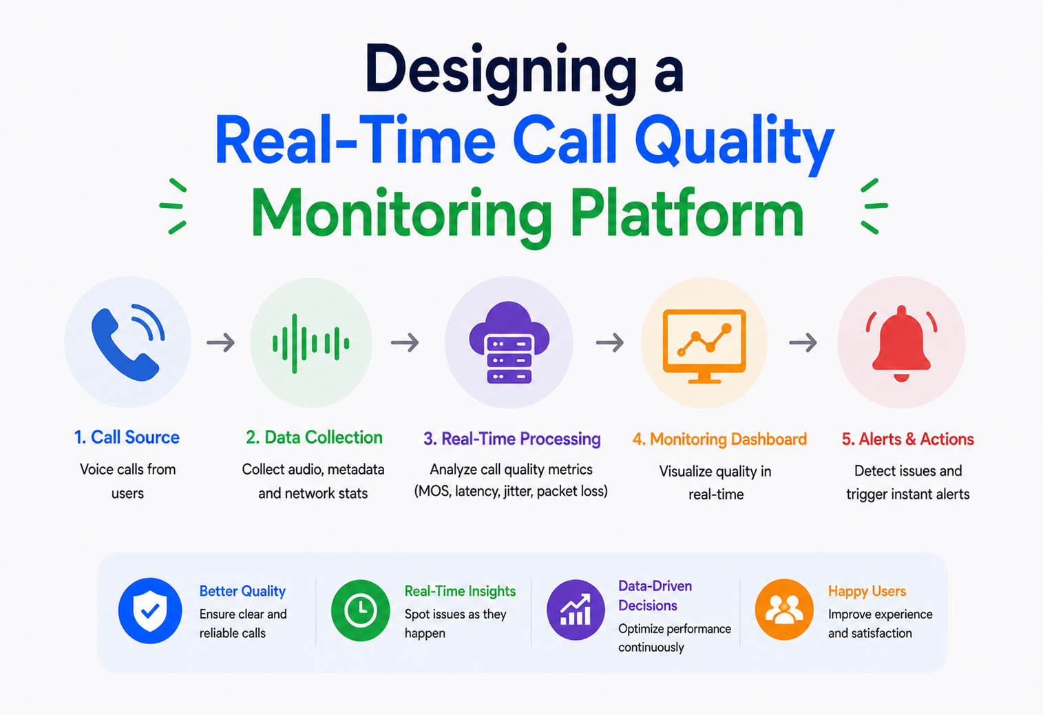
Collects per-call metrics — packet loss, jitter, RTT, estimated MOS — for real-time monitoring and post-call analytics.
graph TB
    subgraph CALLER["Caller Side"]
        A["Maya Client on Fiber"]
    end
    subgraph CALLEE["Callee Side"]
        B["Grandfather Client on 3G"]
    end

    subgraph SIGNAL["Signaling Plane"]
        SIG["Signaling Service"]
        PRES["Presence Service"]
    end

    subgraph NAT["NAT Traversal"]
        STUN["STUN Servers"]
        TURN["TURN Relay Servers"]
    end

    subgraph MEDIA["Media Plane at Nearest Edge PoP"]
        SFU["SFU Media Router"]
        BWE["Bandwidth Estimator"]
    end

    A --> SIG
    SIG --> B
    B --> SIG
    SIG --> A
    A --> STUN
    B --> STUN
    A --> TURN
    B --> TURN
    A --> SFU
    SFU --> B
    SFU --> BWE
    BWE --> SFU
Component deep dive
Signaling Service. Handles everything that happens before and around actual audio flowing — ringing, accepting or declining, exchanging session descriptions (codecs supported, encryption keys, network candidates) between participants using SDP and typically SIP or a proprietary protocol over WebSocket. Critically, signaling does not carry the audio itself, so it can tolerate more latency than the media path can.
STUN and TURN (NAT traversal). Most devices sit behind a NAT (Network Address Translation) router, which means their real network address is hidden from the internet. STUN servers help a client learn its own public-facing address and port by simply asking “what does the internet see when I contact you?” That answer becomes an ICE (Interactive Connectivity Establishment) candidate, allowing peers to try connecting directly. When a direct connection cannot be established — roughly 15 to 20 percent of real-world connections, due to symmetric NAT or restrictive firewalls — a TURN server relays the media instead, at the cost of an extra hop of latency, but as a necessary fallback for connectivity.
Selective Forwarding Unit. For group calls, the SFU is the workhorse. Each participant sends their audio (and video, if applicable) once, uplink, to the SFU. The SFU then forwards each incoming stream to every other participant — without decoding and re-encoding it — which keeps CPU cost low and preserves quality, while still letting the SFU make per-recipient decisions such as which video simulcast layer to forward to each specific viewer, based on their bandwidth.
Bandwidth Estimation Engine. Continuously running, typically on both the sending client and the receiving or relaying side, this component watches metrics like packet arrival timing and loss to estimate how much bandwidth is genuinely available right now, and feeds that estimate back to the encoder so it can raise or lower the audio (and video) bitrate before congestion causes real damage.
“Why use an SFU instead of having every participant send media directly to every other participant (full mesh)?” Full mesh means each client’s upload bandwidth scales with the number of other participants, which breaks down quickly past a handful of people; an SFU centralizes fan-out so each client only uploads once regardless of group size. Follow-up: “When would you use an MCU instead of an SFU?” When you need server-side mixing — for example combining multiple audio streams into one for a legacy phone-bridge participant, or producing a single composited video feed for recording or broadcast — at the cost of more server CPU and a small quality and latency hit from re-encoding.
Internal Working: Codecs, Jitter Buffers & Adaptive Bitrate
Three cooperating mechanisms — the codec, the jitter buffer, and the congestion-control feedback loop — are what actually convert raw audio into an intelligible conversation across an unreliable, ever-changing network.
3.1 Audio codecs
A codec compresses raw audio into far fewer bits before sending, and decompresses it on the other end. The dominant modern choice, Opus, is notable because it is a single codec that can operate anywhere from about 6 kbps (barely-intelligible, extreme low-bandwidth fallback) up to 510 kbps (studio-quality), and — critically for adaptive systems — it can change its bitrate within an active call, packet to packet, without renegotiating the whole session. This is what actually makes real-time adaptation to Maya’s grandfather’s weak 3G signal possible without dropping the call.
3.2 Jitter buffers
Packets do not arrive at perfectly even intervals — network jitter means packet 2 might arrive 20 ms after packet 1, then packet 3 arrives 60 ms after that. If audio were played the instant each packet arrived, this unevenness would sound like stuttering. A jitter buffer deliberately holds a small, adaptively-sized window of incoming packets before playback, smoothing arrival-time variance into a steady playback stream. The core trade-off: a bigger buffer smooths more jitter but adds more end-to-end delay; a smaller buffer feels snappier but is more exposed to audible glitches when jitter spikes. Modern jitter buffers are adaptive — they grow when they observe more jitter and shrink when the network is calm, continuously re-tuning this trade-off in real time.
sequenceDiagram
    participant Network
    participant JB as Adaptive Jitter Buffer
    participant Speaker

    Network->>JB: Packet 1 arrives on time
    Network->>JB: Packet 2 arrives 45 ms late
    Network->>JB: Packet 3 arrives early
    Note over JB: Buffer holds packets briefly then reorders and smooths timing
    JB->>Speaker: Packet 1 at steady interval
    JB->>Speaker: Packet 2 at steady interval
    JB->>Speaker: Packet 3 at steady interval
3.3 Packet loss concealment & forward error correction
On lossy networks — common on mobile or 3G — some packets simply never arrive. Rather than retransmitting (too slow for real-time audio), VoIP systems use two complementary techniques:
- Packet Loss Concealment (PLC): the decoder synthesizes a plausible-sounding replacement for a missing packet based on the audio just before it, rather than leaving silence or a harsh click — modern codecs like Opus have quite sophisticated built-in PLC.
- Forward Error Correction (FEC): the sender proactively includes a small amount of redundant information about recent packets alongside new ones, so if one packet is lost, enough information to reconstruct it (or an approximation of it) may already have arrived inside a later packet.
3.4 Adaptive bitrate & congestion control
This is the mechanism that most directly answers “how does the system maintain quality across varying network conditions.” A congestion control algorithm — Google Congestion Control (GCC) is the most widely used in WebRTC-based systems — continuously estimates available bandwidth using two independent signals: how packet arrival delay is trending (a rising delay trend signals early congestion, even before loss occurs) and the observed packet loss rate. Based on this estimate, it instructs the encoder to raise or lower the target bitrate, typically several times per second.
flowchart LR
    A["Encoder sends audio at current bitrate"] --> B["Receiver measures arrival delay and loss"]
    B --> C["Bandwidth estimator computes available bandwidth"]
    C --> D{"Estimate rising or falling"}
    D -- rising --> E["Feedback increase target bitrate"]
    D -- falling or loss --> F["Feedback decrease target bitrate"]
    E --> G["Encoder adjusts Opus bitrate for next packets"]
    F --> G
    G --> A
By the time packets are actually being dropped, a network is already significantly congested. Watching the delay trend lets the system back off pre-emptively — a proactive rather than reactive control loop — which is why modern congestion control catches degrading conditions earlier than older, loss-only-based approaches.
“Walk me through what happens, step by step, when a call participant’s WiFi suddenly gets congested.” Packet arrival delay starts trending upward, the bandwidth estimator detects this, feedback is sent back to the sender, the sender’s encoder lowers the Opus target bitrate and possibly enables more aggressive FEC, the receiver’s jitter buffer may also grow slightly to absorb the added jitter, and audio quality drops gracefully rather than the call cutting out. Follow-up: “Why not just always send audio at the lowest safe bitrate to avoid ever having this problem?” Because that would waste available bandwidth and needlessly reduce quality for users who have plenty of headroom, like Maya on fiber — the whole point of adaptive bitrate is matching quality to what is actually available, not defaulting to the worst case for everyone.
Data Flow & Call Lifecycle
A single call moves through six distinct phases from the moment the caller hits the button to the moment the call ends — each phase touching different subsystems with very different latency and availability requirements.
flowchart TB
    S1["Caller initiates call"] --> S2["Signaling sends SDP offer"]
    S2 --> S3["Callee device rings and generates SDP answer"]
    S3 --> S4["ICE candidate gathering via STUN"]
    S4 --> S5{"Direct P2P path viable"}
    S5 -- yes --> S6["Media flows peer to peer"]
    S5 -- no --> S7["Media relayed via TURN or SFU"]
    S6 --> S8["Continuous bandwidth estimation and adaptive bitrate"]
    S7 --> S8
    S8 --> S9["Jitter buffering plus PLC and FEC on receive side"]
    S9 --> S10["Audio played to user"]
    S10 --> S11["Call quality telemetry streamed to monitoring"]
    S11 --> S12["Call ends teardown signaling releases resources"]
Call initiation
The caller’s client sends a call request through the signaling service, which notifies the callee (via push notification if the app is not foregrounded) and begins exchanging SDP — a description of supported codecs, encryption parameters, and media capabilities.
ICE negotiation
Both clients gather a set of ICE candidates (local address, STUN-discovered public address, and TURN relay address as a fallback) and exchange them via signaling, then try each candidate pair to find the best-performing viable path.
Media path establishment
If a direct P2P path works, it is preferred for lowest latency. Otherwise, media flows through a relay — a TURN server or a full SFU for group calls at a nearby edge point-of-presence.
Steady-state adaptation
For the call’s duration, bandwidth estimation, adaptive bitrate, jitter buffering, and loss concealment continuously run in a tight feedback loop, re-tuning several times per second as conditions change.
Telemetry
Each client periodically reports quality metrics — loss, jitter, round-trip time, estimated Mean Opinion Score — which feed both real-time monitoring and post-call quality analytics.
Teardown
Either party ending the call triggers signaling to release media resources, close relay allocations, and free SFU forwarding state, so a new call can immediately take that capacity.
Advantages, Disadvantages & Trade-offs
Every architectural choice in a VoIP system is a trade-off between latency, quality, cost, and complexity — and understanding which trade the design accepted tells you far more than any single component name.
| Decision | Advantages | Disadvantages / Trade-offs |
|---|---|---|
| UDP transport for media | Low latency; no head-of-line blocking from retransmissions; ideal for real-time audio. | No delivery guarantee; the app must handle loss itself via FEC and PLC rather than relying on the transport. |
| Peer-to-peer media when possible | Lowest possible latency; reduces server infrastructure cost. | Not always possible behind restrictive NAT or firewalls; harder to apply consistent quality or moderation controls. |
| SFU for group calls | Scales to many participants without multiplying client upload bandwidth; preserves quality because there is no re-encode. | Requires server infrastructure and adds one relay hop of latency versus pure P2P. |
| Large jitter buffer | Smoother audio on unstable networks. | Adds end-to-end delay, which can make conversation feel less natural if overused. |
| Aggressive FEC | Better resilience against packet loss. | Uses more bandwidth even when loss is not currently happening — a cost paid pre-emptively. |
“If P2P is lower latency, why do many production systems route all media through servers even when P2P would work?” Because server-routed media makes it easier to apply consistent recording, moderation, quality monitoring, and simplifies handling network changes or mobile handoffs mid-call — at the cost of an extra hop of latency and infrastructure expense, a deliberate trade many products accept because operability and user experience consistency are worth the small quality tax.
Performance & Scalability
Scaling a VoIP system is not about raising requests per second on a single service — it is about placing infrastructure close to users, fanning out media efficiently, and giving the encoder a way to gracefully degrade before anything breaks.
6.1 Geographic edge placement
Because latency is dominated by physical distance and the number of network hops, the single biggest scalability and quality lever is placing TURN and SFU media relay points-of-presence (PoPs) close to users, in many regions globally, and routing each call through the PoP nearest to its participants — often using anycast routing or latency-based DNS geo-routing to automatically direct clients to the nearest healthy PoP.
6.2 Simulcast & layered encoding
Primarily a video technique, but conceptually similar to how adaptive audio works. For group calls, rather than encoding once and hoping it fits every recipient’s bandwidth, senders can encode multiple quality layers simultaneously (simulcast), letting the SFU forward the appropriate layer to each recipient based on their individual bandwidth — a viewer on a weak connection gets a lower layer while others get full quality, all from the same sender, without the sender needing per-recipient encodes.
6.3 SFU cascading for very large calls
A single SFU instance has a practical ceiling on concurrent participants, bounded by CPU and network throughput for fan-out. For very large calls (hundreds of participants and up), production systems cascade multiple SFUs together — participants connect to their nearest regional SFU, and SFUs forward selected streams to each other, keeping most fan-out local while still merging all participants into one logical call.
graph TB
    subgraph ASIA["Region Asia"]
        SFU1["SFU Asia PoP"]
        P1["Participants in Asia"]
    end
    subgraph EU["Region Europe"]
        SFU2["SFU Europe PoP"]
        P2["Participants in Europe"]
    end
    subgraph AMER["Region Americas"]
        SFU3["SFU Americas PoP"]
        P3["Participants in Americas"]
    end
    P1 --> SFU1
    SFU1 --> P1
    P2 --> SFU2
    SFU2 --> P2
    P3 --> SFU3
    SFU3 --> P3
    SFU1 --> SFU2
    SFU2 --> SFU1
    SFU2 --> SFU3
    SFU3 --> SFU2
    SFU1 --> SFU3
    SFU3 --> SFU1
6.4 Server capacity planning
Media relay throughput scales primarily with concurrent call-minutes and per-call bitrate, not request count in the traditional web-service sense — capacity planning models bandwidth and packet-forwarding CPU cost per concurrent call, and auto-scales PoP capacity based on real-time concurrent call volume by region, with headroom for regional traffic spikes (for example, a national holiday driving a surge of calls in one country).
“How would you design capacity planning for New Year’s Eve, when call volume spikes massively in each timezone in sequence?” Use the predictable timezone-rolling nature of the spike to pre-scale each region’s PoP capacity ahead of its local midnight, rather than reacting purely to real-time load, combined with cross-region overflow capacity as a safety margin. Reactive auto-scaling alone tends to lag the spike by minutes, which is unacceptable when the spike itself lasts only a few minutes.
High Availability & Reliability
Availability in a VoIP system means more than “the service accepts requests.” It means active calls survive real-world events: WiFi to cellular handoffs, PoP failures, and signaling outages, all without the user watching a call drop.
7.1 Mid-call network handoff
Mobile users routinely switch from WiFi to cellular mid-call (walking out of a building). A reliable system detects the local network change, re-gathers ICE candidates, and performs an ICE restart to re-establish the best media path — ideally without the user perceiving any interruption beyond a brief quality dip. This is one of the biggest differentiators between a professional VoIP product and a hobby prototype.
7.2 PoP and relay failover
Each regional PoP should be deployed with redundant SFU and TURN instances behind a fast health-checked routing layer. If a PoP or instance becomes unhealthy mid-call, active calls can be migrated to a healthy instance, though in practice many systems accept a brief call quality glitch or, in worst cases, a call re-establishment, since call state is inherently harder to seamlessly migrate than stateless web traffic.
7.3 Signaling redundancy
The signaling service, while less latency-sensitive than media, must still be highly available — a signaling outage prevents new calls from being set up even if existing calls’ media paths are fine. Signaling is typically built as a stateless, horizontally-scaled service backed by a replicated presence and session store, deployed across multiple availability zones.
Once a call’s media path is established directly between clients or through a specific relay, that specific relay instance holds live per-call state (forwarding rules, current bitrate targets); this makes media infrastructure meaningfully “statefuller” than typical stateless microservices, and failover strategy must account for that. You cannot just round-robin a new request to any instance mid-call the way you would a stateless API call.
“What happens to an active call if its assigned TURN server crashes?” The call typically detects the loss via missed keepalives or an RTP timeout, triggers ICE restart, re-gathers candidates including a new TURN allocation from a healthy server, and re-establishes the media path — usually perceived by users as a brief glitch or short silence rather than a full dropped call, if the client implements ICE restart correctly.
Security
Voice is uniquely sensitive: it carries private conversations, it often traverses third-party infrastructure like a TURN relay, and its billing paths can be abused for real financial loss. Security is not a bolt-on here — it is threaded through every layer.
SRTP + DTLS-SRTP
Voice packets are encrypted in transit using SRTP with keys negotiated via DTLS during call setup, protecting against eavesdropping even when media is relayed through third-party infrastructure like a TURN server.
TLS on WebSocket / HTTPS
Signaling traffic — call setup and SDP exchange — runs over TLS-protected WebSocket or HTTPS, preventing call metadata and session parameters from being intercepted or tampered with.
Scoped TURN Credentials
TURN relay credentials should be short-lived and scoped to a specific call or session, so a leaked credential cannot be reused to relay unrelated, potentially abusive traffic through your infrastructure.
DoS Protection
Signaling endpoints and TURN allocation requests need rate limiting per user and per IP, since call setup and relay allocation are more expensive operations than a typical API call and a more attractive DoS target.
Toll Fraud Prevention
For systems bridging to the traditional phone network (PSTN), strict authorization and anomaly detection on outbound calling patterns prevents compromised accounts from being used to place expensive international calls at the platform’s cost.
“Does encrypting media add meaningful latency?” Modern encryption, especially with hardware acceleration on mobile SoCs and modern server CPUs, adds negligible latency compared to network transmission time itself — encryption is essentially never the bottleneck in a well-implemented system, and the security benefit is enormous.
Monitoring, Logging & Metrics
You cannot improve what you cannot measure, and in a VoIP system, quality regressions are otherwise invisible until user complaints arrive — which is far too late. Telemetry is the difference between a system engineers can operate and one they can only apologize for.
| Metric | Why it matters |
|---|---|
| Packet loss rate (per call, per leg) | Direct driver of audio quality degradation; sudden spikes indicate network or infrastructure problems. |
| Jitter (ms) | Indicates network stability; feeds jitter buffer sizing decisions. |
| Round-trip time (RTT) | Baseline latency floor; high RTT limits how responsive a call can ever feel regardless of other tuning. |
| Mean Opinion Score (MOS), estimated | A standardized 1 to 5 estimate of perceived call quality, computed from loss, jitter, and delay — the closest proxy to “did this call sound good.” |
| Call setup success rate & time-to-connect | Measures signaling and ICE negotiation health — failures here mean users cannot even start talking. |
| ICE candidate pair success rate (P2P vs TURN fallback) | Tracks how often calls need relay fallback, informing infrastructure and NAT-traversal investment decisions. |
| SFU/TURN instance CPU & bandwidth utilization | Core capacity signal for auto-scaling and regional headroom planning. |
Per-call quality telemetry is typically streamed both in near-real-time (to detect and potentially react to in-call degradation, or trigger automated alerts for infrastructure issues) and aggregated for post-call analytics dashboards, letting engineering teams spot systemic regressions (for example, “MOS scores for calls routed through the São Paulo PoP dropped starting Tuesday”) that are invisible in any single call.
Both matter for different questions. Real-time telemetry catches acute incidents (a PoP going bad right now); aggregated post-call telemetry catches slow, systemic regressions (a codec change that made calls two percent worse everywhere). A mature VoIP platform invests in both pipelines and treats them as first-class engineering surfaces.
Deployment & Cloud Architecture
Deployment for VoIP looks different from deploying a typical web service: geography is a first-class citizen, media servers are meaningfully stateful, and canary rollouts have to notice qualitative regressions, not just error rates.

- Signaling services are deployed as stateless, auto-scaled services across multiple availability zones, typically fronted by WebSocket-aware load balancers with sticky session support for the duration of an active signaling connection.
- SFU/TURN media infrastructure is deployed to many geographically distributed PoPs (often dozens globally for a large-scale product), sized for regional concurrent-call capacity, using bare-metal or specialized compute where raw packet-forwarding throughput and predictable performance matter more than typical container-orchestration flexibility.
- Geo-routing (anycast IP or latency-based DNS) automatically directs each client to its nearest healthy PoP at call setup time, re-evaluated on ICE restart if network conditions change mid-call.
- Canary rollout for media server software is especially critical — a subtle regression in the bandwidth estimator or jitter buffer logic can degrade call quality in ways that are hard to catch in pre-production testing, so gradual regional rollout with close MOS-score monitoring is standard practice.
graph TB
    DNS["Latency Based Geo DNS or Anycast"] --> POPA["PoP Asia SFU plus TURN"]
    DNS --> POPE["PoP Europe SFU plus TURN"]
    DNS --> POPU["PoP Americas SFU plus TURN"]
    SIGSVC["Global Signaling Service Multi AZ"] --> POPA
    SIGSVC --> POPE
    SIGSVC --> POPU
    TELEM["Call Quality Telemetry Pipeline"] --> POPA
    TELEM --> POPE
    TELEM --> POPU
Databases, Caching & Load Balancing
Different pieces of a VoIP system need very different storage backends. Getting the match right avoids a common failure mode where a single-database mindset gets forced onto a set of workloads that have almost nothing in common.
11.1 Presence & session state
Presence — who is online, who is currently in a call, which device — is highly mutable, read-heavy data best served from a low-latency, replicated key-value store (Redis or similar), not a traditional relational database, since it needs sub-millisecond lookups during call setup and frequent updates as users’ states change.
11.2 Call metadata & history
Call records (who called whom, duration, quality summary) are comparatively low-volume, write-once, append-style data well suited to a standard relational or wide-column store, since it is queried more for analytics, billing, and history display than for hot-path real-time decisions.
11.3 Telemetry storage
Per-call quality metrics are naturally time-series data (many small numeric samples over the duration of each call), well suited to a time-series database or columnar store optimized for aggregation queries like “average MOS score by region by day.”
11.4 Load balancing
Signaling connections use standard sticky WebSocket load balancing. Media relay “load balancing” is really a routing and placement decision made once at call setup time (which PoP, which specific SFU or TURN instance) based on real-time capacity and proximity — not a per-packet load-balancing decision, since a single call’s media must consistently flow through the same relay instance for the call’s duration.
APIs & Microservices
The service boundaries in a VoIP system are chosen so that signaling logic (call setup, business rules) can evolve independently of the packet-forwarding data plane, which needs different skills, deployment cadence, and infrastructure.
Call Setup API
Initiates calls, manages the ringing / accept / decline state machine, and orchestrates the SDP handshake between participants.
Signaling / SDP Exchange
Relays SDP offers, answers, and ICE candidates between participants over a WebSocket connection kept open for the call’s duration.
STUN Service
Lightweight, stateless, typically using standard open-source implementations (for example, coturn), because a broken STUN service silently sinks connectivity for millions of users.
TURN Allocation Service
Issues short-lived, scoped relay credentials and allocates relay resources per call, freeing them promptly when the call ends.
SFU Control Plane
Manages which SFU instance or region serves a given call, tracks per-participant forwarding state, and exposes APIs for the client to subscribe or unsubscribe to specific participants’ streams.
Telemetry Ingestion API
Receives periodic quality reports from clients and media servers, feeding both real-time alerting and historical analytics pipelines.
These services are deliberately decoupled: signaling and call-setup logic can be iterated on and deployed independently of the performance-critical, often lower-level media relay path, and the media infrastructure can be scaled purely based on regional call volume without needing to understand call-setup business logic at all.
Design Patterns & Anti-Patterns
The patterns below are the ones that keep showing up across every serious VoIP product; the anti-patterns are the ones that keep sinking projects that ignored them.
Patterns to use
Selective Forwarding (SFU)
The standard scalable approach to multi-party media routing without server-side transcoding cost.
Adaptive Feedback Loop
Continuous measure, estimate, and adjust cycles — bandwidth estimation feeds bitrate adjustment — rather than static, one-time configuration.
Graceful Degradation
Reducing bitrate, disabling video, or simplifying audio quality under poor conditions rather than dropping the call entirely.
Edge Placement / Anycast
Minimizing physical distance between participants and relay infrastructure as a primary latency lever.
Circuit Breaker for Relay Health
Automatically routing new call setups away from an unhealthy PoP or relay instance so a bad node cannot poison the fleet.
Anti-patterns to avoid
- Use TCP for the media path. Retransmission-induced delay is worse for real-time audio than simply tolerating and concealing small amounts of loss.
- Fix the bitrate. A non-adaptive rate forces every participant down to worst-case quality, or conversely causes stutter for anyone below the fixed rate — it defeats the entire purpose of designing for varying network conditions.
- Do full-mesh P2P for group calls. Client upload bandwidth requirements scale linearly with participant count, breaking down well before call sizes most products need to support.
- Route all global traffic through one central region. This adds unnecessary round-trip latency for users far from that region and defeats the purpose of investing in adaptive quality if the baseline latency floor is already too high.
- Couple call setup and media delivery. Treating them as one tightly bound system makes it harder to scale, deploy, and reason about each independently, and conflates very different latency and availability requirements.
Best Practices & Common Mistakes
The gap between a demo-quality VoIP prototype and a production-quality one is almost entirely made up of the practices below — and the mistakes on the other side of the ledger.
Best practices
- Always design for the fallback path (TURN relay, lower codec bitrate, PLC) as a first-class scenario, not an edge case — real-world networks are messy far more often than system designers initially assume.
- Instrument call quality telemetry from day one; you cannot improve what you cannot measure, and quality regressions are otherwise invisible until user complaints arrive.
- Test explicitly under simulated poor network conditions (packet loss, jitter, bandwidth caps) as part of standard CI, not just on ideal office WiFi.
- Keep signaling and media infrastructure independently deployable and scalable.
- Prefer proactive delay-trend-based congestion signals over purely reactive loss-based ones, catching degradation earlier.
Common mistakes
- Assuming lab or office network testing represents real-world conditions — mobile networks, congested WiFi, and international routes behave very differently.
- Over-sizing jitter buffers “just to be safe,” inadvertently adding noticeable, unnecessary conversational delay.
- Ignoring NAT traversal failure rates — a system that works great in testing (usually on open networks) can fail unexpectedly often for real users behind restrictive corporate or carrier-grade NAT.
- Under-provisioning TURN relay capacity, since a meaningful fraction of real-world calls (not a rare exception) require relaying, not just direct P2P.
Real-World Industry Examples
Every major real-time communication product on the internet has independently converged on roughly the same architecture — adaptive codec, SFU-based routing, WebRTC-style transport, and a global edge network — which is strong evidence the approach described here is the durable one.
Global Voice & Video Calling
WhatsApp’s calling infrastructure is built to handle enormous global scale with users on highly variable network quality, leaning heavily on Opus’s wide adaptive bitrate range and aggressive network-condition-aware adaptation, given its huge base of users in regions with less reliable mobile networks.
Global Multi-Datacenter Media Routing
Zoom operates a large global network of data centers and dynamically routes each meeting’s media through the lowest-latency healthy path available, with an SFU-style architecture for its multi-party meetings and simulcast-style layered encoding so a single sender’s stream can serve viewers with very different bandwidth simultaneously.
WebRTC-Native Design
Built directly on WebRTC, Google Meet benefits from that standard’s built-in Opus codec support, DTLS-SRTP encryption, and Google’s own congestion control research (Google Congestion Control originated from this ecosystem), tightly integrated with Google’s global network backbone for edge routing.
Voice Channels at Scale
Discord’s persistent, always-available voice channels — as opposed to explicitly scheduled calls — required particular attention to fast call setup and join latency and efficient SFU resource use, given users frequently join and leave voice channels throughout a session rather than placing discrete, deliberate calls.
Traditional PSTN Bridging
Many VoIP products also bridge to the traditional phone network for dial-in and dial-out functionality, requiring gateway infrastructure that translates between internet-based SIP and RTP and the PSTN’s own signaling and audio formats — a good illustration of how new distributed-systems techniques still often need to interoperate with decades-old, fundamentally different infrastructure.
Frequently Asked Questions
The questions below are the ones most commonly asked in real interviews and design reviews about this system.
Reliability in TCP’s sense means guaranteed, in-order delivery via retransmission — but retransmission adds delay, and for real-time voice, a late packet is often worse than a lost one. UDP lets the application decide how to handle loss (via FEC and PLC) rather than forcing a one-size-fits-all retransmission delay on every lost packet, which is the wrong default for a real-time medium.
MOS is a standardized 1 (bad) to 5 (excellent) subjective quality rating, originally gathered from human listener panels. Modern systems estimate it automatically using models (such as the E-model, ITU-T G.107) that take measured network conditions — packet loss, jitter, delay — as input and output a predicted MOS, giving an objective, continuously-computable proxy for subjective call quality.
During ICE negotiation, all viable candidate pairs (direct and relay-based) are gathered and tested; the system prefers the lowest-latency working direct path, falling back automatically to a TURN relay only when no direct path succeeds, which typically happens due to symmetric NAT or restrictive firewalls.
The core mechanisms — adaptive bitrate, jitter buffering, loss concealment, SFU-based routing — apply to both, but video adds additional techniques like simulcast and scalable video coding (multiple quality layers) because video’s bandwidth needs are far larger and more variable than audio’s, making per-recipient quality tailoring more impactful.
Significantly. The speed of light imposes a hard floor on round-trip latency regardless of bandwidth, so even a theoretically “perfect,” uncongested long-distance connection (for example, across an ocean) has a noticeably higher latency floor than a local one, which is precisely why geographically distributed edge PoPs matter so much for global call quality.
The client’s local IP has changed, so its old ICE candidates are stale. It re-runs ICE candidate gathering (local address, STUN-discovered public address, and TURN allocation as a fallback), signals the new candidates to the remote peer, and both sides converge on the best new candidate pair — ideally in under a second, so the user hears only a brief quality dip rather than a dropped call.
Because every millisecond in the jitter buffer is a millisecond of added conversational delay, and conversation quality collapses well before people consciously notice why. Adaptive jitter buffers grow only as much as the observed jitter actually requires, which is the smallest-safe delay possible, rather than a static over-provisioned one.
Summary & Key Takeaways
A production VoIP system exists to defend a single user-visible property: two people, on wildly different networks, should be able to hear each other clearly and in real time. Every architectural choice in this tutorial follows from that one goal.
Voice calling is a real-time medium where timeliness matters more than perfect delivery. The entire system architecture, from UDP transport to loss concealment, follows from this core principle — and the biggest first-time-designer mistake is importing a web-request mental model into a real-time domain where it does not apply.
Quality is maintained across varying networks through a continuous adaptive feedback loop: bandwidth estimation informs codec bitrate, jitter buffer sizing, and FEC aggressiveness, all re-tuned multiple times per second per participant. Anything static in this loop is a bug waiting to hurt users.
The Opus codec’s wide adaptive range and WebRTC’s standardized stack — ICE, STUN, TURN for connectivity; DTLS-SRTP for encryption; RTP and RTCP for media transport and feedback — form the practical foundation most modern VoIP products build on, and interoperating with that ecosystem is almost always cheaper than reinventing pieces of it.
SFU-based architecture is the standard scalable solution for group calls, avoiding both the bandwidth explosion of full-mesh P2P and the quality and latency cost of full server-side mixing (MCU), reserving MCU-style mixing for specific needs like legacy phone bridging.
Geographic edge placement of relay infrastructure is the single largest lever on baseline latency, since physical distance imposes a hard floor no amount of algorithmic cleverness can overcome. A globally competitive product simply has to invest here.
Security (SRTP/DTLS encryption, scoped TURN credentials) and observability (loss, jitter, RTT, estimated MOS) are not afterthoughts — they are integral to a system where quality is dynamic, invisible when working, and immediately noticed by users when it is not.
Industry leaders (WhatsApp, Zoom, Google Meet, Discord) all converge on the same core architecture — WebRTC-based transport and encryption, SFU-based group routing, adaptive bitrate, and globally distributed edge infrastructure — validating it as the proven approach to this problem.
Key takeaways an interviewer wants to hear
- Voice favors timeliness over completeness — that is why VoIP runs on UDP with FEC and PLC, not TCP.
- Adaptation is continuous, not one-shot. Bitrate, jitter buffer size, and FEC aggressiveness re-tune many times per second per participant.
- Signaling and media are separate systems with different latency, availability, and scaling requirements.
- SFU is the default for multi-party. Full-mesh P2P does not scale; MCU costs quality and latency.
- Physical distance is a hard latency floor. Edge PoPs are the biggest lever on baseline quality.
- Watch delay trend, not just loss. Reacting only to loss reacts too late.
- Instrument from day one. MOS, jitter, RTT, and ICE success rate are the first-class quality signals.
- Design for the fallback path. A meaningful fraction of real-world calls do not get direct P2P, so TURN and lower-bitrate codec modes are load-bearing, not exceptional.