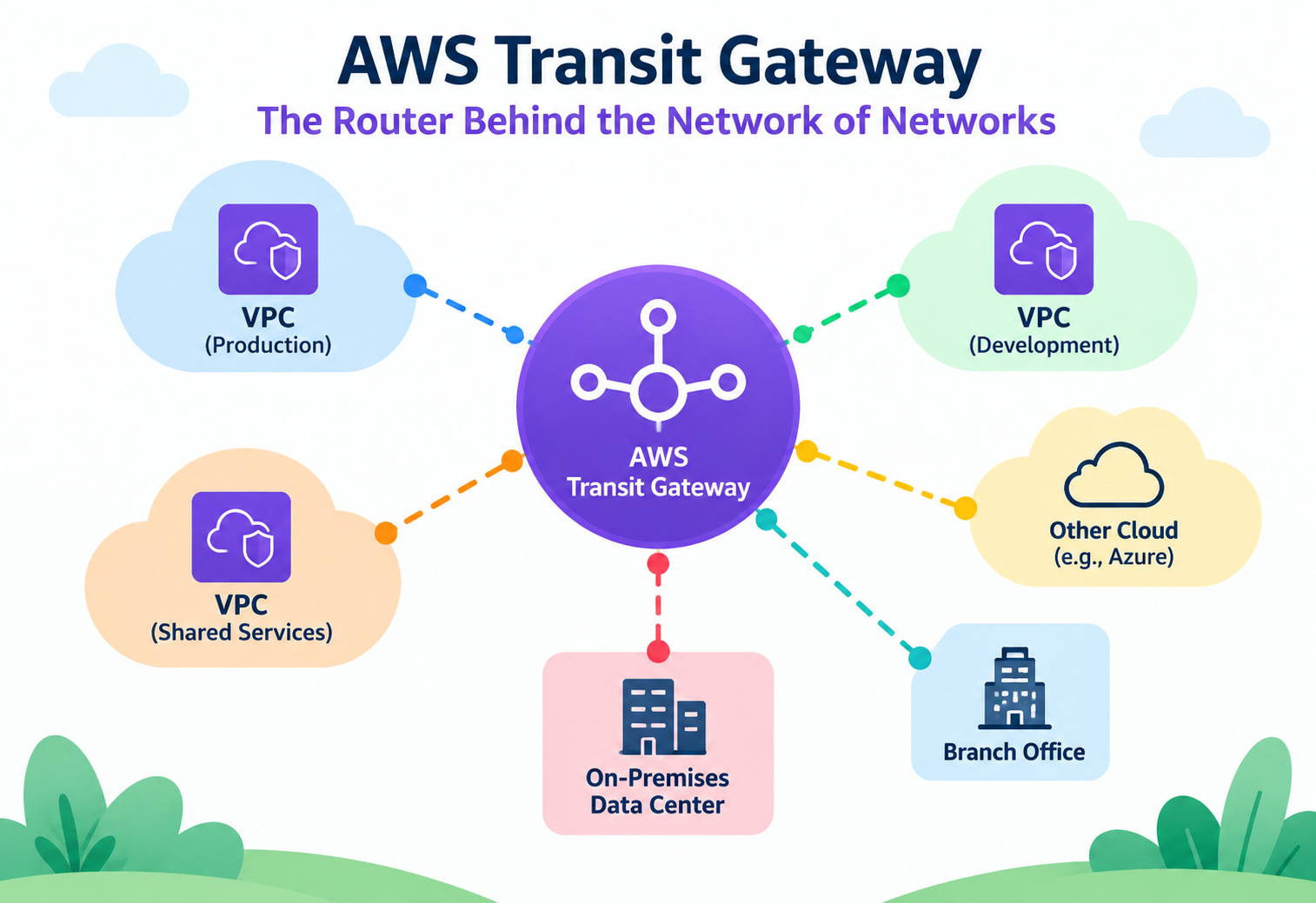
AWS Transit Gateway – The Router Behind the Network of Networks
How AWS Transit Gateway actually routes traffic between dozens of VPCs and on-premises networks — its route table model, attachment types, and the segmentation patterns real organizations use to keep a hub-and-spoke network both scalable and safe.
Imagine an airport with a single central terminal where every regional airline lands, and from that one terminal, ground crews decide exactly which gate each incoming flight can connect onward to — some passengers can reach any gate, others are restricted to just a few, all controlled by rules set at the terminal, not by the individual airlines. That central terminal is a fair picture of what AWS Transit Gateway does for a cloud network. Instead of every VPC negotiating its own private connection to every other VPC, they all connect once to a shared hub, and that hub decides who can reach whom. This tutorial goes past “it connects VPCs together” and into how Transit Gateway’s route tables, attachments, and propagation model actually behave — the details that matter once a network has grown past a handful of VPCs.
1Core Concepts Beyond the Basics
Once you know Transit Gateway “connects lots of VPCs together,” the real design work begins with understanding attachments and route tables as separate, composable objects.
A Transit Gateway itself is just a regional router with no traffic-forwarding opinions of its own until things are attached to it. An attachment represents one connection into the Transit Gateway — a VPC, a Site-to-Site VPN, a Direct Connect gateway, or a peering connection to a Transit Gateway in another region. Each attachment is associated with exactly one Transit Gateway route table at a time, and that route table decides where traffic arriving from that attachment is allowed to go next.
Think of Transit Gateway route tables like different visitor badges issued at that central airport terminal. A “staff” badge (route table) lets you walk to any gate. A “connecting passenger” badge only lets you reach the gates for your specific onward flight. Both badge types pass through the same terminal, but the terminal’s rules — not the badge holder’s intentions — decide where each badge can actually go.
Association versus propagation: two verbs that mean different things
This distinction confuses more engineers than almost anything else in Transit Gateway design. Association determines which route table an attachment uses to look up where to send its outbound traffic — each attachment has exactly one association. Propagation determines which route tables automatically learn routes to that attachment’s network — an attachment can propagate its routes into many route tables at once, letting other attachments reach it, without those other attachments necessarily being able to send traffic anywhere that attachment could.
An attachment can be associated with one route table but have its routes propagated into several different ones. This asymmetry is exactly what makes one-way visibility patterns — like a shared services VPC that everyone can reach but that can’t reach everything else — possible.
Why this matters more than it seems to at first
Every serious network segmentation strategy on Transit Gateway — separating production from non-production, isolating a security-inspection VPC, or giving a partner network limited access — is implemented entirely through the combination of which route table an attachment is associated with and which route tables its routes are propagated into. There’s no separate “segmentation feature” bolted on top; segmentation is just a deliberate arrangement of these two primitives.
2Architecture and Core Components
A Transit Gateway deployment is built from a small set of object types, each with a specific, narrow job.
Transit Gateway
A regional, highly available router that attachments connect to. It has no traffic-forwarding behavior of its own beyond what its route tables define.
Attachments
VPC attachments, VPN attachments, Direct Connect gateway attachments, and peering attachments to Transit Gateways in other regions.
Transit Gateway Route Tables
Independent from VPC route tables — these decide, per attachment, where traffic entering the Transit Gateway is allowed to exit.
Appliance Mode
An attachment setting that keeps bidirectional flows pinned to the same Availability Zone’s network appliance, important for stateful inspection devices.
graph TD
  VPC1[Production VPC] -->|Attachment| TGW((Transit Gateway))
  VPC2[Shared Services VPC] -->|Attachment| TGW
  VPC3[Non-Prod VPC] -->|Attachment| TGW
  VPN[Site-to-Site VPN] -->|Attachment| TGW
  DXGW[Direct Connect Gateway] -->|Attachment| TGW
  TGW --> RT1[Production Route Table]
  TGW --> RT2[Shared Services Route Table]
  TGW --> RT3[Non-Prod Route Table]
One Transit Gateway, many route tables
A single Transit Gateway commonly hosts several route tables simultaneously — one per network segment that needs different reachability rules. This is fundamentally different from a VPC’s route table model, where each subnet typically has one route table reflecting one policy; here, the same physical hub can enforce several distinct policies at once, simply by grouping attachments under different route tables.
Peering attachments span regions, not just VPCs
Beyond connecting VPCs within a region, Transit Gateways in different AWS Regions can peer with each other, extending the same hub-and-spoke model globally. Traffic between peered Transit Gateways travels over AWS’s private backbone rather than the public internet, giving cross-region connectivity without a separate VPN or Direct Connect setup.
3Internal Working: How a Route Actually Gets Chosen
Understanding the exact order Transit Gateway evaluates routes in explains almost every “why can’t A reach B” support case.
Static versus propagated routes, and priority between them
A Transit Gateway route table can hold routes two ways: propagated automatically from an attachment’s CIDR range, or added manually as a static route. When both a static route and a propagated route exist for the same destination, the static route takes priority — a detail that matters when someone adds a “temporary” static route to redirect traffic and later can’t understand why propagation changes elsewhere in the network stopped having any visible effect.
Longest prefix match, same as VPC routing
Just like a VPC route table, a Transit Gateway route table selects the most specific matching route for a destination, not the first one added. This lets a broad “send everything to the inspection VPC” route coexist safely with narrower, more specific routes to particular spoke VPCs, with the narrower route always winning when both could apply.
People sometimes expect Transit Gateway to automatically make every attached VPC reachable from every other one. It does not — reachability only exists where propagation and association have been deliberately configured to allow it. A missing propagation entry is one of the most common causes of “the attachment exists but traffic still doesn’t flow.”
Equal-cost multi-path (ECMP) for VPN redundancy
When multiple VPN tunnels or attachments provide equally good paths to the same destination, Transit Gateway can load-balance traffic across them using ECMP, rather than treating one as strictly primary and the other as a cold standby. This is part of why pairing two VPN tunnels through Transit Gateway yields both redundancy and aggregate throughput, not just failover.
4Data Flow and Lifecycle
Tracing one packet from a spoke VPC to a shared services VPC through the hub shows exactly where each configuration piece takes effect.
Packet leaves the spoke VPC’s subnet
The spoke VPC’s own route table sends traffic destined outside its CIDR range to its Transit Gateway attachment.
Transit Gateway checks the attachment’s associated route table
The specific route table that this spoke’s attachment is associated with is consulted for a destination match.
Longest prefix match selects the exit attachment
The most specific matching route points to the shared services VPC’s attachment as the next hop.
Traffic exits toward the shared services VPC
The packet leaves the Transit Gateway through the shared services attachment and enters that VPC’s own route table for final delivery.
Return traffic follows the same lookup, in reverse
The shared services VPC’s attachment consults its own associated route table to find its way back to the original spoke.
Why both directions need to work independently
Because each attachment has its own association, reachability isn’t automatically symmetric. A spoke VPC being able to reach a shared services VPC doesn’t guarantee the reverse is true — the shared services attachment’s own route table needs a route back to that spoke, either through propagation or a static entry, or return traffic simply has nowhere to go once it reaches the hub.
5Advantages, Disadvantages and Trade-offs
Transit Gateway trades a mesh of pairwise connections for a single hub — a trade that scales beautifully until the hub’s own limits start to matter.
Advantages
- Replaces an exponentially growing peering mesh with a linear number of attachments.
- Independent route tables allow fine-grained, per-segment traffic policies from one central hub.
- Cross-region peering extends the same model globally over AWS’s private backbone.
- Centralizes egress and inspection patterns without duplicating NAT or firewall infrastructure per VPC.
- Highly available by design, spanning multiple Availability Zones within a region automatically.
Disadvantages / Trade-offs
- Adds a per-GB data processing charge for traffic crossing the Transit Gateway, which can be significant at scale.
- Route table design complexity grows with the number of segments a network needs, requiring careful planning.
- A misconfigured route table affects every attachment associated with it, so mistakes have a wider blast radius than a single VPC’s route table error.
- All traffic between VPCs now depends on a shared, central resource rather than direct peer connections.
The trade-off in one sentence
Transit Gateway exchanges the operational simplicity of many independent, isolated connections for the manageability of one central point of control — a clearly good trade once a network passes a handful of VPCs, and arguably unnecessary overhead below that.
6Performance and Scalability
Transit Gateway scales to very large attachment counts, but a few specific per-attachment limits shape how workloads should be distributed.
Per-attachment bandwidth is the real ceiling
Each individual VPC attachment has its own burst bandwidth ceiling, and a single flow (one source-destination-port combination) doesn’t exceed that per-attachment limit no matter how large the underlying instances are. Workloads pushing very high throughput between two VPCs sometimes need multiple parallel flows, or an architecture that spreads load across more than one attachment, to actually use the aggregate bandwidth Transit Gateway can support.
Multicast Support
Transit Gateway can also act as a multicast router within a region, letting a single stream reach multiple subscriber VPCs — a niche but important capability for media distribution and certain financial market-data feeds that would otherwise need duplicate point-to-point streams.
Route table limits shape segmentation design
The default limit on route tables per Transit Gateway is generous but finite, and it directly caps how many independent network segments a single Transit Gateway can cleanly express. Very large organizations sometimes need multiple Transit Gateways, connected via peering, specifically to work around this ceiling rather than cramming every segment into one gateway’s route tables.
7High Availability and Reliability
Transit Gateway itself is resilient by design, which shifts most of the availability responsibility onto how attachments are configured underneath it.
Multi-AZ VPC attachments
A VPC attachment to Transit Gateway should include a subnet in every Availability Zone the VPC’s workloads use. Skipping an AZ’s subnet from the attachment forces cross-AZ traffic for anything in that zone, adding both latency and inter-AZ data transfer cost — a subtle mistake that doesn’t cause an outage but quietly degrades performance and increases the bill.
Transit Gateway attachments are billed and provisioned per Availability Zone included, so “just attach every subnet to be safe” isn’t free — it’s a deliberate trade between resilience, latency, and cost that should be made per workload.
VPN redundancy through dual tunnels and ECMP
Each Site-to-Site VPN connection provisions two tunnels over physically diverse paths by default. Combined with Transit Gateway’s ECMP support, both tunnels can be active simultaneously rather than one sitting idle as a cold standby, improving both resilience and effective throughput for VPN-connected sites.
Cross-region resilience through peering
For disaster recovery across AWS regions, peering two Transit Gateways lets a secondary region’s spoke VPCs reach shared services or on-premises connectivity that only exists in the primary region — though the peering connection itself becomes a dependency worth monitoring and, for critical paths, worth designing a fallback around.
8Security
Because Transit Gateway sits at the center of an organization’s network, its route table design is one of the highest-leverage security controls in the whole environment.
Segmentation through route table isolation
The primary security pattern on Transit Gateway is deliberately separate route tables per trust boundary — production, non-production, a partner network, a security inspection zone — with propagation carefully scoped so that, for example, a partner attachment can only reach the one shared service it needs, never the full internal network.
| Segment | Associated Route Table | Can Reach |
|---|---|---|
| Production VPCs | Production RT | Shared services, each other |
| Non-production VPCs | Non-Prod RT | Shared services only |
| Partner VPN | Partner RT | One designated shared service, nothing else |
Centralized egress inspection
A common pattern routes all outbound internet traffic from every spoke VPC through a central inspection VPC’s firewall appliances before it reaches an internet gateway, using Transit Gateway route tables to force that path rather than trusting each spoke to run its own NAT and firewall consistently. Appliance mode, mentioned earlier, is important here specifically to keep both directions of a flow pinned to the same appliance instance for correct stateful inspection.
Problem
Associating every attachment with a single, shared “default” Transit Gateway route table that propagates all routes into itself, as a quick way to get everything talking to everything.
Why It’s Harmful
This collapses every intended network boundary into one flat, fully-open network, which defeats the purpose of having separate production, non-production, and partner environments in the first place, and is very hard to unwind later without an outage.
Correct Approach
Design route tables around trust boundaries from the start, even if the initial rule set is generous — it’s far easier to loosen a deliberately scoped design than to retrofit segmentation onto a flat one.
9Monitoring, Logging and Metrics
Because Transit Gateway sits between networks rather than inside one, visibility tooling has to be pointed at the hub deliberately — it isn’t automatically covered by per-VPC monitoring.
Transit Gateway Flow Logs
Records accepted and rejected traffic passing through the Transit Gateway itself, separate from VPC-level Flow Logs.
CloudWatch Metrics
Bytes and packets in/out per attachment, useful for spotting an attachment approaching its bandwidth ceiling before it becomes a bottleneck.
AWS Network Manager
Visualizes Transit Gateway attachments, peering, and on-premises connections across regions and accounts as one topology map.
Route Table Analysis
Periodically reviewing propagation and static route entries against intended segmentation, since drift here is invisible until traffic actually flows somewhere unexpected.
Assuming VPC Flow Logs already capture everything relevant to a Transit Gateway-routed connection. Transit Gateway Flow Logs are a distinct feature, and skipping them leaves a genuine blind spot right at the point where most cross-network traffic actually passes through.
10Deployment and Multi-Account Design
Transit Gateway is almost always a multi-account concern in practice, and AWS provides specific mechanisms for sharing it safely across an organization.
AWS Resource Access Manager (RAM)
Lets a central networking account share a Transit Gateway with other accounts in an organization, so each team can attach their own VPC without owning the hub.
Direct Connect Gateway Integration
Associates a Direct Connect gateway with a Transit Gateway, letting on-premises networks reach every attached VPC through one dedicated physical connection.
Centralized Network Account
A common landing-zone pattern where the Transit Gateway, its route tables, and shared services all live in one account that application teams don’t have write access to.
Who owns the route tables matters as much as who owns the hub
Sharing the Transit Gateway itself via RAM doesn’t automatically give attaching accounts control over route table design — that’s usually kept centralized precisely so that a single application team can’t accidentally (or deliberately) reroute traffic meant for another segment. Deployment design here is as much an organizational-permissions decision as a networking one.
11Design Patterns and Anti-patterns
A small number of route table arrangements cover most real-world Transit Gateway deployments.
Pattern: Segmented Hub-and-Spoke
Separate route tables per environment (production, staging, sandbox), each propagating into a shared services route table, but not into each other — the most common enterprise starting point.
Pattern: Centralized Egress
All spoke route tables send 0.0.0.0/0 to an inspection VPC’s attachment, which alone holds the route to an internet gateway or NAT gateway, funneling all outbound traffic through one auditable choke point.
Pattern: Global Transit via Peering
Regional Transit Gateways peered together, each handling its own regional segmentation, connected specifically for the shared services or disaster-recovery traffic that genuinely needs to cross regions.
Problem
Treating Transit Gateway as a one-time setup task rather than an evolving piece of infrastructure, leaving route tables undocumented and changed ad hoc as new VPCs are attached.
Why It’s Harmful
Because route tables enforce security boundaries, undocumented drift here is effectively undocumented drift in the organization’s actual security posture — a gap that’s usually only discovered during an audit or an incident, not before.
Correct Approach
Manage Transit Gateway route tables as infrastructure-as-code with change review, the same discipline applied to security groups or IAM policies, since the blast radius of a mistake here is comparable.
12Best Practices and Common Mistakes
Most Transit Gateway problems trace back to a small number of overlooked defaults in how attachments and route tables were wired together.
Advantages
- Design route table segmentation before attaching the first VPC, not after growth forces a retrofit.
- Attach a subnet from every Availability Zone a VPC actually uses, to avoid silent cross-AZ latency and cost.
- Enable Transit Gateway Flow Logs from day one, alongside VPC-level Flow Logs.
- Use appliance mode whenever traffic passes through a stateful inspection or NAT appliance.
Disadvantages / Trade-offs
- Associating everything with one flat route table “to keep things simple,” erasing intended segmentation.
- Forgetting that association and propagation are separate settings, leading to one-directional reachability nobody intended.
- Not accounting for per-GB data processing costs when estimating the price of moving large volumes of traffic through the hub.
- Leaving route table changes undocumented, making later audits or incident response far slower than necessary.
When a new segment (like a partner connection) is added, testing reachability using Reachability Analyzer against the intended route table design before turning on real traffic tends to surface propagation gaps far faster than waiting for a support ticket.
13Real-world and Industry Examples
Organizations reach for Transit Gateway at a specific, recognizable moment — usually right as their VPC peering mesh becomes unmanageable.
Enterprises Consolidating Cloud Landing Zones
Large enterprises with dozens of application teams commonly centralize connectivity through Transit Gateway as part of a broader multi-account landing zone, pairing it with AWS Organizations and RAM for governed, self-service VPC attachment.
Financial Institutions with Segmented Compliance Zones
Regulated organizations use Transit Gateway route table segmentation to keep in-scope compliance environments (like cardholder data environments) reachable only from the specific systems that legitimately need access, with everything else explicitly excluded through propagation design.
Media and Broadcast Using Multicast
Some media and financial market-data platforms use Transit Gateway’s multicast support to distribute a single live stream to many subscriber VPCs simultaneously, avoiding redundant point-to-point streaming infrastructure.
14Frequently Asked Questions
Association decides which single route table an attachment uses to send its own outbound traffic. Propagation decides which route tables automatically learn how to reach that attachment — an attachment can propagate into several route tables while being associated with only one.
No. Reachability only exists where the route tables involved have the right propagation and association configured. Attaching alone just makes the connection to the hub possible, not automatic mutual visibility.
Yes, through Transit Gateway peering, which connects Transit Gateways in different regions over AWS’s private backbone rather than the public internet.
Reasons include exceeding a single Transit Gateway’s route table limit, wanting fully separate blast-radius domains for different business units, or organizational boundaries that call for administratively distinct hubs even within one region.
Without appliance mode, the two directions of a single connection’s traffic could be routed to different Availability Zones’ worth of a stateful appliance, breaking inspection or NAT state tracking. Appliance mode pins both directions to the same AZ’s appliance instance.
Traffic between VPCs through Transit Gateway travels over AWS’s private network, not the public internet, but that is not the same as encryption. Attachments over the public internet, like Site-to-Site VPN, are encrypted at the VPN layer; VPC-to-VPC traffic through Transit Gateway itself is not separately encrypted unless the workload encrypts it.
15Summary and Key Takeaways
AWS Transit Gateway replaces a growing tangle of pairwise VPC connections with a single, central hub — but the value of that hub comes entirely from how deliberately its route tables are designed. Association and propagation, working together, are the only mechanisms shaping which parts of a network can see and reach which other parts; there’s no separate segmentation feature layered on top. Teams that design route table boundaries around real trust zones from the outset, monitor the hub with its own dedicated Flow Logs, and treat route table changes with the same rigor as security policy changes get a network that scales to hundreds of connections without losing the isolation it started with.
Key Takeaways
- Association and propagation are separate concepts — one attachment, one association, but potentially many propagation targets, and mixing them up is the top cause of unexpected reachability.
- Route tables enforce segmentation directly — there’s no separate policy layer; the route table design is the security boundary.
- Longest prefix match and static-route priority govern which route wins when more than one could apply, identical in principle to VPC routing.
- Per-attachment bandwidth is the real scaling limit, not the Transit Gateway itself — plan for multiple flows or attachments for very high-throughput paths.
- Multi-AZ attachment coverage avoids silent cross-AZ latency and cost, and should be a deliberate per-workload decision.
- Centralized egress and inspection patterns depend on appliance mode to keep stateful traffic flowing correctly through a shared appliance.
- Route table changes deserve the same review discipline as IAM or security group changes, since they shape the entire network’s trust boundaries.