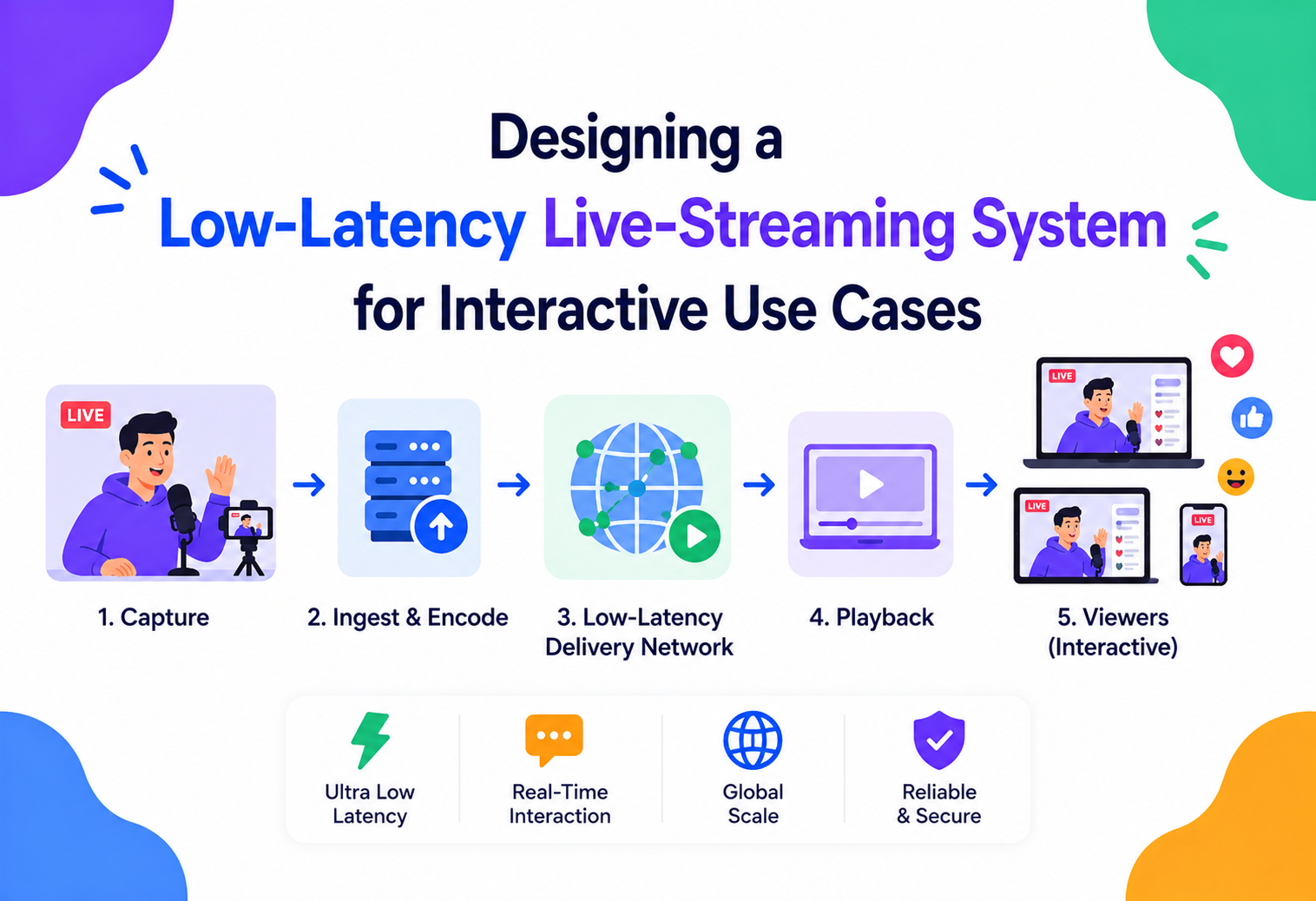
Designing a Low-Latency Live-Streaming System for Interactive Use Cases
How do you get a bid, a raised hand, or an auctioneer’s hammer to appear on thousands of viewers’ screens in well under a second? A deep, interview-grade walkthrough of building a glass-to-glass sub-second live streaming pipeline for real-time interactive experiences like live auctions, live shopping, and interactive game shows.
Introduction & History
Think about a live auction happening online. The auctioneer raises a hand and says “going once, going twice.” A bidder watching from home needs to see and hear that moment almost instantly, form a decision, and place a bid — all before the hammer falls. If the video the bidder is watching is even three or four seconds behind reality, they might place a bid on an item that has already sold, or miss the window entirely.
This is fundamentally different from watching a recorded show or even a typical live sports broadcast, where a 20 to 30 second delay is invisible and harmless to the viewer’s experience. In an interactive live-streaming scenario, latency is not a quality-of-service metric buried in a dashboard — it is the core product experience.
1.1 Where the streaming stack comes from
Traditional internet video streaming, built on protocols like HLS (HTTP Live Streaming) and MPEG-DASH, was designed around the mid-2000s to solve a completely different problem: reliably delivering video to enormous, unpredictable audiences over ordinary HTTP infrastructure, using CDNs, with buffering used liberally to smooth over network jitter. That design achieves massive scale and rock-solid playback stability, but at the cost of 6 to 30 or more seconds of latency, because each video segment must be fully encoded, packaged, uploaded, and then downloaded by the player in chunks before playback.
Interactive live streaming pulls from a different lineage entirely: real-time communication technology originally built for video calling — protocols like WebRTC (Web Real-Time Communication), designed around peer-to-peer and low-latency media transport with sub-second delivery as a first-class goal.
1.2 One-to-many broadcast at conversational latency
The system we are designing here sits at the intersection of these two worlds: it needs the massive fan-out scale of broadcast streaming (thousands to millions of simultaneous viewers watching one broadcaster) combined with the sub-second latency characteristics of real-time communication. This combination — one-to-many broadcast at conversational latency — is one of the hardest and most interesting problems in modern media systems engineering, and is exactly what powers live auction platforms, live shopping and commerce streams, interactive game shows, and remote sports betting broadcasts.
By the end of this tutorial, you will understand how video and audio travel from a broadcaster’s device, through an ingest and distribution pipeline, out to a global audience, in well under one second — and how that pipeline stays reliable, secure, and cost-efficient at massive scale.
“Why cannot you just use standard HLS with a small segment size to reduce latency?” — Shrinking HLS segments reduces latency somewhat (this is the basis of Low-Latency HLS), but you are still bound by segment-based, pull-based HTTP delivery: the player must wait for a segment to be fully written before requesting it. For true sub-second interactivity, you need push-based, continuously flowing media transport — which is what WebRTC-style architectures provide.
Requirements
Every downstream architectural decision in this document is anchored to the requirements below. Nailing them precisely up front is what turns “live streaming, but faster” into a concrete engineering target.
2.1 Functional requirements
- A broadcaster (auctioneer, host) can start a live video / audio stream from a browser, mobile app, or professional encoder.
- Viewers can join an ongoing stream and see and hear the broadcast with glass-to-glass latency well under one second (target: 200 – 800 ms depending on tier and network conditions).
- Viewers can send low-latency interactive signals back — bids, reactions, chat — that the broadcaster and other viewers see almost immediately.
- The system must scale from a handful of viewers to potentially hundreds of thousands or millions of concurrent viewers on a single popular stream.
- Support for adaptive quality — viewers on poor networks get a lower-bitrate stream automatically, without breaking synchronization with the live moment.
- Recording / DVR of the stream for later replay, without compromising the live path’s latency.
- Fairness and ordering guarantees for time-sensitive interactions (for example, which bid arrived “first” in an auction) even though different viewers experience slightly different latencies.
2.2 Non-functional requirements
Ultra-low, predictable
Both the average and the tail (p99) matter, since a single slow viewer bidding “late” due to network variance is a fairness problem, not just a UX annoyance.
Massive fan-out
One broadcaster’s stream must be efficiently distributed to potentially millions of viewers without the ingest path bearing that fan-out cost directly.
High availability
A dropped stream during a live auction has real financial consequences; the system must recover gracefully from broadcaster network blips, server failures, and regional outages.
Regionally consistent latency
Viewers across continents should experience comparably low latency, not just viewers near the broadcaster.
Synchronization
All viewers should see the “live edge” (the most current moment) within a tight window of each other, so that a bid placed by one viewer is meaningfully comparable in time to a bid from another.
Efficient at scale
Real-time media transport is significantly more expensive per viewer-hour than traditional CDN delivery, so the architecture must control this cost deliberately.
2.3 Back-of-envelope estimation
Assume a platform running 5,000 concurrent live auction / shopping streams at peak, averaging 2,000 concurrent viewers per stream (with some “hero” streams reaching 500,000+) — roughly 10 million concurrent viewer connections at peak. At a typical adaptive bitrate ladder averaging 2.5 Mbps effective per viewer, that is around 25 Tbps of egress bandwidth at absolute peak, which is precisely why the distribution layer (Chapter 3) must be built on a globally distributed edge network rather than a small number of centralized media servers. Interaction traffic (bids, reactions) is comparatively tiny in bandwidth but latency-critical: even at 10 million viewers each sending a handful of small real-time messages per minute, this is on the order of a few hundred thousand messages per second — well within reach of a well-designed real-time messaging layer, but demanding on connection-count and fan-out design.
Architecture & Components
The architecture separates into four cooperating layers: ingest, real-time processing, distribution, and an interaction layer. Keeping the interaction layer architecturally separate from the media path is essential — a bid must never wait behind a video frame in a queue, and a media pipeline hiccup must never silently drop a bid.
3.1 The four cooperating layers
Getting media in
Terminates the broadcaster’s connection close to them geographically, authenticates the stream, and hands off to the processing pipeline.
Real-time transcoding
Decodes, transcodes, and packages the incoming stream into an adaptive bitrate ladder suited to varied network conditions.
Edge fan-out
Fans the stream out to potentially millions of viewers via a cascading tree of edge Selective Forwarding Units, with minimal added delay.
Bidirectional signalling
The low-latency channel for bids, reactions, and chat that runs alongside — but architecturally independent of — the media path.
flowchart TB
    subgraph Broadcaster["Broadcaster Side"]
        ENC["Broadcaster App or Encoder"]
    end

    subgraph Ingest["Ingest Layer"]
        ISFU["Ingest SFU RTMP WebRTC Gateway"]
        AUTH["Stream Auth Service"]
    end

    subgraph Processing["Real Time Media Processing"]
        TRANS["Real Time Transcoder (ABR Ladder)"]
        MIX["Media Mixer Composer (optional overlays)"]
    end

    subgraph Distribution["Distribution Edge Layer"]
        ORIGIN["Media Origin Cluster"]
        EDGE1["Edge PoP Region A"]
        EDGE2["Edge PoP Region B"]
        EDGE3["Edge PoP Region C"]
    end

    subgraph Interaction["Interaction Layer"]
        RTC["Realtime Messaging Cluster"]
        SEQ["Sequencer Event Ordering Service"]
        AUCTION["Auction Engine"]
    end

    subgraph Clients["Viewer Clients"]
        V1["Viewer Region A"]
        V2["Viewer Region B"]
        V3["Viewer Region C"]
    end

    subgraph Support["Support Services"]
        DVR["DVR Recording Service"]
        ANALYTICS["QoE Analytics"]
    end

    ENC --> AUTH
    AUTH --> ISFU
    ISFU --> TRANS
    TRANS --> MIX
    MIX --> ORIGIN
    ORIGIN --> EDGE1
    ORIGIN --> EDGE2
    ORIGIN --> EDGE3
    EDGE1 --> V1
    EDGE2 --> V2
    EDGE3 --> V3
    ORIGIN --> DVR
    V1 -.-> RTC
    V2 -.-> RTC
    V3 -.-> RTC
    RTC --> SEQ
    SEQ --> AUCTION
    AUCTION --> RTC
    EDGE1 --> ANALYTICS
    EDGE2 --> ANALYTICS
    EDGE3 --> ANALYTICS
3.2 Component responsibilities
| Component | Responsibility |
|---|---|
| Stream Auth Service | Authenticates and authorizes a broadcaster before ingest begins; issues short-lived stream tokens and keys. |
| Ingest SFU / Gateway | Accepts incoming media (typically WebRTC, sometimes RTMP or SRT for professional encoders), terminates the connection close to the broadcaster geographically to minimize first-mile latency. |
| Real-Time Transcoder | Produces an adaptive bitrate (ABR) ladder of the stream in real time, so viewers with different network capacities can each get a stream they can sustain without buffering. |
| Media Origin Cluster | The authoritative, first point of aggregation for the processed stream, pushing it onward to edge points of presence. |
| Edge PoPs (SFU / CDN) | Geographically distributed nodes that terminate viewer connections close to the viewer, minimizing last-mile latency and fanning out to many viewers per edge node without each viewer connection tracing back to the origin. |
| Realtime Messaging Cluster | Handles the bidirectional low-latency channel for bids, reactions, and chat, entirely independent of the media pipeline’s path and timing. |
| Sequencer / Event Ordering Service | Establishes a canonical, fair order for time-sensitive events like bids, resolving the reality that different viewers see the “live moment” at slightly different wall-clock times. |
| Auction Engine | Domain-specific logic: validates bid amounts, enforces auction rules (minimum increment, “going once and twice”), and is the source of truth for who currently holds the highest bid. |
| QoE Analytics | Continuously measures glass-to-glass latency, rebuffer events, and edge health, feeding both dashboards and automated routing decisions. |
“Why is the Auction Engine not just part of the media pipeline?” — Because bidding is business logic with strict correctness and fairness requirements (money, ordering, validation), while the media pipeline is a best-effort, loss-tolerant real-time transport system. Coupling them would force the media path to inherit strict consistency requirements it does not need, and would force the auction logic to depend on the availability of video infrastructure it should not need to care about.
Internal Working
To minimize end-to-end latency, you first need to know exactly where it accumulates. This chapter breaks the pipeline down stage by stage, then covers the specific mechanisms — SFUs, layered ABR, media-synchronized timestamps, and congestion control — that keep the whole thing coherent.
4.1 The anatomy of glass-to-glass latency
| Stage | Typical contribution | Key optimization |
|---|---|---|
| Capture and encode (broadcaster device) | 10 – 50 ms | Low-latency encoder settings, short GOP, hardware encoding. |
| First-mile network (broadcaster to ingest) | 10 – 100 ms | Geographically nearby ingest point, UDP-based transport (not TCP) to avoid head-of-line blocking. |
| Real-time transcode | 20 – 80 ms | Hardware-accelerated, parallel ABR ladder generation, avoiding multi-pass encoding. |
| Distribution / fan-out | 20 – 150 ms | Edge PoPs close to viewers; media relayed, not re-encoded, at the edge wherever possible. |
| Last-mile network (edge to viewer) | 10 – 100 ms | Nearest edge PoP selection, UDP transport, congestion control tuned for real-time media. |
| Client buffering and jitter buffer | 50 – 300 ms | The single largest controllable lever — an aggressive (small) jitter buffer trades resilience to network jitter for lower latency. |
| Decode and render | 5 – 30 ms | Hardware decoding, minimal render pipeline overhead. |
4.2 Media transport: push, not pull
Traditional streaming (HLS / DASH) is fundamentally a pull model: the player requests discrete file segments over HTTP, one at a time, and must wait for each to exist before it can be fetched. This is inherently latency-adding because a segment must be fully written (commonly 2 – 6 seconds) before the first byte can even be requested. Real-time architectures instead use a push model over UDP-based transport (SRTP within WebRTC, or the QUIC-based transports underlying newer low-latency protocols): media flows continuously as it is produced, packet by packet, with no requirement to wait for a discrete chunk boundary. This is the foundational reason WebRTC-based pipelines can achieve sub-second latency while segment-based streaming fundamentally cannot, no matter how aggressively segment sizes are tuned.
4.3 Selective Forwarding Units (SFUs) and fan-out
A naive real-time architecture might try to use full peer-to-peer mesh connections (every viewer connects directly to the broadcaster), which collapses immediately past a handful of viewers because the broadcaster’s upload bandwidth would need to scale linearly with viewer count. Instead, the system uses Selective Forwarding Units (SFUs): media servers that receive one (or a small number of) incoming stream from the broadcaster and relay — not re-encode — that stream to many connected viewers. Because relaying is far cheaper than transcoding, a single SFU instance can fan a stream out to thousands of directly connected viewers with minimal added latency (typically single-digit milliseconds of relay overhead).
For the truly massive fan-out required by a viral auction stream (hundreds of thousands of viewers), a single SFU is not enough — the architecture forms a tree or mesh of SFUs across edge locations: the origin SFU sends the stream to a small number of regional edge SFUs, each of which fans out to its local viewers. This cascading SFU topology is the real-time-media equivalent of a CDN’s origin-to-edge hierarchy, and is what allows the system to serve millions of viewers while adding only one or two extra relay hops (each contributing single-digit to low-double-digit milliseconds) regardless of total audience size.
flowchart TB
    B["Broadcaster"] --> O["Origin SFU"]
    O --> R1["Regional SFU US"]
    O --> R2["Regional SFU EU"]
    O --> R3["Regional SFU APAC"]
    R1 --> V1["Thousands of Viewers US"]
    R2 --> V2["Thousands of Viewers EU"]
    R3 --> V3["Thousands of Viewers APAC"]
4.4 Adaptive bitrate without adding latency
Standard ABR (adaptive bitrate streaming) in traditional streaming switches between independently encoded quality renditions at segment boundaries, which works well when segments are multiple seconds long, but does not translate directly to a low-latency, continuously flowing stream. Instead, real-time ABR uses simulcast (the broadcaster’s client encodes and sends multiple quality layers simultaneously, and the SFU forwards only the appropriate layer to each viewer based on their network conditions) or scalable video coding (SVC) (a single encoded stream contains layered quality that can be selectively forwarded, adding a base layer plus optional enhancement layers). Because layer selection happens per-viewer at the SFU — a cheap forwarding decision, not a re-encode — a viewer’s network degrading does not require a new encode or add any transcoding latency; the SFU simply starts forwarding a lower layer already being produced.
4.5 Solving the “fair bid ordering” problem
This is the crux of what makes an interactive auction system uniquely hard, beyond generic low-latency streaming. Even with excellent optimization, different viewers will always experience the live moment at slightly different times — a viewer with a 50 ms network path sees the auctioneer’s hammer moment slightly before a viewer with a 200 ms path. If both viewers react to the same visual moment and place a bid, their bids arrive at the server at different times purely due to network variance, not because one viewer was genuinely faster to react. A naive “first bid received wins” design would systematically and unfairly favor viewers with better network conditions.
The Sequencer / Event Ordering Service addresses this by attaching a synchronized media timestamp to every bid — not just the server-arrival time, but the timestamp of the video frame the viewer was watching when they initiated the bid (the client embeds this in the bid payload, derived from the same clock driving playback). The Auction Engine can then reason about bids in terms of “how many milliseconds after the relevant moment did this viewer react,” which is a far fairer basis for tie-breaking than raw network arrival time. This does not eliminate the physics of speed-of-light and network latency, but it converts an unfair “who has the better internet connection” contest into a much fairer “who reacted faster relative to what they actually saw” comparison, and is exactly the kind of subtlety that distinguishes a naively built interactive streaming system from a production-grade one.
“Two bidders click ‘bid’ at what looks like the same instant on their own screens — how do you decide who wins?” — Attach a media-synchronized timestamp (not wall-clock arrival time) to each bid on the client, and let the Auction Engine compare reaction time relative to the broadcast moment, applying a well-defined, disclosed tie-breaking rule (for example, earliest synchronized timestamp, with a small fairness window) rather than raw server arrival order.
4.6 Clock synchronization across broadcaster, server, and viewer
Making the media-synchronized-timestamp approach work in practice requires solving a smaller but equally important problem: the broadcaster’s device clock, the server’s clock, and every viewer’s device clock are all independently drifting, unsynchronized clocks. The system addresses this using a technique similar to NTP (Network Time Protocol): each client periodically exchanges lightweight round-trip timing probes with a server it is connected to, allowing it to estimate both its clock offset from server time and the one-way network delay to that server. The media timestamp embedded in outgoing packets (and in bid payloads) is expressed in this server-synchronized time base rather than the device’s raw local clock, so that a bid’s timestamp is comparable across devices with completely different, independently drifting clocks. This is a deceptively subtle piece of infrastructure — without it, the fairness model from Section 4.5 would simply be comparing meaningless, mutually inconsistent numbers.
4.7 Congestion control for real-time media
Standard TCP congestion control (designed to maximize throughput and avoid network collapse for bulk data transfer) is a poor fit for real-time media, where the priority is minimizing delay, not maximizing eventual throughput. Real-time transport instead uses congestion control algorithms purpose-built for interactive media (such as Google Congestion Control, commonly used within WebRTC implementations), which continuously estimate available bandwidth from packet arrival timing and loss patterns, and proactively signal the sender to reduce its target bitrate before the network queue builds up enough to add meaningful delay. This is the mechanism that ultimately drives the simulcast / SVC layer-selection decisions described in Section 4.4 — congestion control estimates what a given network path can sustain right now, and the SFU or client adapts which quality layer is requested accordingly, continuously, rather than only reacting after a stall has already occurred.
Data Flow & Lifecycle
A single stream moves through a small set of well-defined lifecycle states, and each live viewer’s session follows a predictable eight-step path from auth to playback.
5.1 Stream lifecycle
stateDiagram-v2
    [*] --> Provisioned
    Provisioned --> Ingesting: Broadcaster connects and authenticates
    Ingesting --> Live: First frames validated transcoding started
    Live --> Degraded: Packet loss or bitrate drop detected
    Degraded --> Live: Network recovers
    Live --> Reconnecting: Broadcaster connection drops
    Reconnecting --> Live: Broadcaster reconnects within grace window
    Reconnecting --> Ended: Grace window expires
    Live --> Ended: Broadcaster stops stream
    Ended --> Archived: DVR processing complete
5.2 End-to-end walkthrough (media path)
- Authentication: The broadcaster’s app requests a stream token from the Stream Auth Service, which validates their identity and permissions and issues a short-lived credential plus the nearest ingest endpoint (selected via geo-routing / anycast).
- Ingest: The broadcaster’s client establishes a low-latency connection (WebRTC, or RTMP / SRT for professional hardware encoders) to the nearest Ingest SFU, and begins pushing continuous audio / video packets — no waiting for a “segment” to complete.
- Real-time transcode: The Real-Time Transcoder consumes the incoming stream and produces a simulcast / SVC ABR ladder in parallel, using hardware acceleration to keep processing latency in the tens-of-milliseconds range.
- Origin aggregation: The processed stream lands at the Media Origin Cluster, the authoritative source for this stream session.
- Edge fan-out: Origin pushes the stream to regional Edge PoPs proactively (for popular / anticipated streams) or on first-viewer-demand (for smaller streams), each edge SFU then relaying to its locally connected viewers.
- Viewer join: A viewer’s client resolves the nearest healthy edge PoP (via geo-DNS or anycast plus real-time health checks), establishes a connection, and begins receiving the stream at the layer matching their measured network capacity.
- Continuous adaptation: Throughout playback, the client continuously reports network conditions; the edge SFU adjusts which simulcast / SVC layer it forwards, and the client’s adaptive jitter buffer tunes itself based on observed packet jitter.
- Parallel interaction path: Independently, the viewer’s client maintains a connection to the Realtime Messaging Cluster for bids / reactions / chat, timestamped against the same media clock as described in Section 4.5.
Live shopping platforms that let viewers “tap to buy” the exact item currently being shown by a host face an almost identical problem to live-auction bidding: the interaction (a purchase) must be unambiguously tied to a specific, narrow moment in the broadcast (which product was being shown), which is exactly why the media-synchronized-timestamp approach from Section 4.5 generalizes well beyond pure auctions to any “time-critical action tied to a live visual moment” product.
Protocol Deep Dive
The protocol choices here are non-obvious and consequential. TCP is a poor fit for real-time media, and no single protocol is the right answer for every viewer — the best systems use a mix, deliberately.
6.1 Why UDP-based transport wins for real-time media
TCP guarantees reliable, in-order delivery — but that guarantee is precisely the problem for real-time media. If a single TCP packet is lost, TCP will pause delivery of every subsequent packet until the lost one is retransmitted and received (head-of-line blocking), even if those later packets have already arrived. For real-time video, a single lost frame is often better handled by simply skipping it (the decoder conceals it or waits for the next keyframe) than by stalling the entire stream waiting for a retransmission that, by the time it arrives, describes a moment that is no longer “live.” This is why real-time media transport is built on UDP (via SRTP / RTP within WebRTC, or newer QUIC-based approaches that get UDP’s flexibility with some of TCP’s reliability primitives applied selectively), which allows the application layer to decide, frame by frame, how much reliability actually matters.
6.2 Comparing the protocol landscape
| Protocol / Approach | Typical Latency | Best Fit |
|---|---|---|
| Traditional HLS / DASH | 6 – 30+ seconds | Massive-scale, non-interactive VOD-like live streaming (news, general entertainment). |
| Low-Latency HLS (LL-HLS) / LL-DASH | 2 – 5 seconds | Large-scale live streaming needing moderate interactivity (live sports with social chat) without sub-second requirements. |
| WebRTC-based SFU architecture | 200 ms – 1 second | Truly interactive use cases: live auctions, live shopping, interactive game shows, remote coaching. |
| Peer-to-peer WebRTC mesh | < 200 ms (small scale only) | Video calls, small-group interactive sessions — does not scale to broadcast audiences. |
6.3 Hybrid delivery strategy
Many production systems use a tiered delivery strategy rather than a single protocol for every viewer: the broadcaster and any viewers who need true sub-second interactivity (active bidders, for example) are served over the WebRTC / SFU path, while viewers who are purely spectating and do not need to act within the interactive window can be served a slightly higher-latency (1 – 3 second) LL-HLS stream, which is dramatically cheaper to distribute at massive scale because it can leverage standard HTTP CDN infrastructure rather than dedicated real-time media servers. The Auction Engine only needs to accept bids from clients that are demonstrably on the low-latency path, which naturally segments the audience by their actual interactivity needs rather than paying the higher cost of real-time infrastructure for every single viewer.
Tier assignment itself can be dynamic rather than fixed at join time. A viewer who joins purely to spectate might later tap “place a bid,” at which point the client seamlessly upgrades its connection from the LL-HLS path to the WebRTC / SFU path, ideally with the transition happening fast enough (typically well under a second) that the viewer does not perceive an interruption. This dynamic upgrade path is what allows the platform to keep steady-state infrastructure costs low across a mostly-passive audience while still guaranteeing that any viewer who wants to participate actively gets the full low-latency experience the moment they need it, rather than forcing a product-level choice between “spectator mode” and “bidder mode” at the start of the session.
Choice made: Serve active and potential bidders over WebRTC / SFU; serve passive spectators over cheaper LL-HLS / CDN delivery.
Why: Real-time SFU infrastructure costs meaningfully more per viewer-hour than CDN-based HTTP delivery. For a viral stream with hundreds of thousands of viewers where only a small fraction are actively bidding at any moment, uniformly serving everyone over the expensive path is a significant, avoidable cost with no corresponding UX benefit for passive viewers.
Advantages, Disadvantages & Trade-offs
The interactive streaming architecture is powerful precisely because of what it commits to — and every one of those commitments carries a real cost worth acknowledging up front.
Sub-second interactivity
Enables genuinely interactive experiences (bidding, live shopping) that are simply impossible with traditional streaming.
Fan-out at scale
Cascading SFU topology scales fan-out to millions of viewers while adding only minimal extra latency per hop.
Adaptive without re-encode
Layered / simulcast ABR adapts to network conditions without any re-encoding cost or added latency.
Isolated failure domains
Separating the media path from the interaction path means a media hiccup never blocks a bid, and vice versa.
Expensive per viewer-hour
Real-time media infrastructure (SFUs, dedicated edge capacity) is significantly more expensive per viewer-hour than standard CDN delivery.
UDP operational surface
UDP-based transport must handle packet loss, NAT traversal, and firewall traversal explicitly — considerably more operational complexity than plain HTTP delivery.
Fairness is hard
Achieving fairness for time-sensitive interactions (Section 4.5) is a genuinely hard distributed-systems problem, not a solved, off-the-shelf capability.
Less jitter tolerance
Lower latency generally means less buffering headroom, so the system is inherently less tolerant of network jitter — a trade-off that must be actively managed, not ignored.
Performance & Scalability
Scaling this system means scaling three very different things: a small, latency-critical ingest path, a massive, cost-driven fan-out path, and an interaction layer whose payloads are tiny but whose connection count is enormous.
8.1 Scaling the ingest path
Ingest is typically the least scale-constrained part of the system, since there is only ever one (or a small number of) broadcaster stream per event, but it is the most latency-sensitive to get right — every millisecond added here is inherited by every single viewer downstream. Ingest points are deployed at many geographic locations so a broadcaster always connects to a nearby one, and anycast routing or intelligent geo-DNS ensures this happens automatically without the broadcaster’s app needing hardcoded endpoint logic.
8.2 Scaling the fan-out path
This is where the bulk of scaling engineering effort goes. Key techniques:
- Cascading SFU trees (Section 4.3) keep the fan-out factor per node bounded and predictable, so adding capacity for a viral stream is a matter of adding more regional / edge SFU capacity, not re-architecting.
- Predictive pre-warming: for anticipated high-profile streams (a major scheduled auction event), edge capacity is provisioned ahead of time rather than reactively scaled, since reactive autoscaling has inherent latency that can cause the first wave of viewers to experience degraded quality.
- Viewer-count-aware layer selection: edge SFUs bias toward forwarding a smaller number of distinct simulcast / SVC layers when viewer count is extremely high, trading a small amount of per-viewer quality optimization for a large reduction in encoding / forwarding overhead at the edge.
8.3 Scaling the interaction layer
The Realtime Messaging Cluster must handle potentially millions of concurrent connections with very high fan-out for broadcast events (a bid update needs to reach every viewer of that auction almost instantly). This is architecturally similar to the realtime fan-out problem in other systems: connections are sharded across many messaging nodes, viewers subscribe to a topic per stream / auction, and updates are published once and fanned out by the messaging layer’s internal pub / sub rather than the Auction Engine pushing individually to every connected viewer.
flowchart LR
    BID["New Highest Bid"] --> TOPIC["Topic auction stream id"]
    TOPIC --> N1["Messaging Node 1"]
    TOPIC --> N2["Messaging Node 2"]
    TOPIC --> N3["Messaging Node N"]
    N1 --> C1["Connected Viewers Shard 1"]
    N2 --> C2["Connected Viewers Shard 2"]
    N3 --> C3["Connected Viewers Shard N"]
8.4 Capacity planning walkthrough
Continuing the earlier estimate of roughly 10 million concurrent viewer connections and around 25 Tbps of peak egress: no single data center can economically or physically serve this from one location, which is why the edge PoP count and per-PoP capacity become the primary scaling knob. If each edge PoP is provisioned to comfortably handle 50,000 – 100,000 concurrent viewer connections, serving 10 million concurrent viewers requires on the order of 100 – 200 active edge PoPs distributed globally — consistent with the scale of real-world CDN and real-time media networks. For the interaction layer, at a few hundred thousand messages per second peak, a cluster of messaging nodes each handling tens of thousands of connections and moderate message throughput per node is sufficient, since bid / reaction payloads are tiny (well under 1 KB) compared to video traffic.
“A single auction stream unexpectedly goes viral and jumps from 5,000 to 500,000 viewers in two minutes — what breaks first, and how do you prevent it?” — The most likely first failure is edge PoP saturation in the region where the spike originates, since reactive autoscaling of media infrastructure has real provisioning latency. Mitigations include headroom-based capacity buffers on every edge PoP, automatic overflow routing to neighboring regional PoPs, and load-shedding rules that gracefully downgrade new joiners to the cheaper LL-HLS tier (Section 6.3) rather than failing connections outright once WebRTC / SFU capacity is exhausted.
High Availability & Reliability
Reliability engineering here is asymmetric on purpose: the media path deliberately tolerates loss to stay fast, while the interaction path deliberately trades a little latency for stronger delivery guarantees. Getting that asymmetry right is what keeps the whole system honest.
9.1 Broadcaster-side resilience
A broadcaster’s network dropping mid-auction is a serious failure mode, so the Ingest layer maintains a short reconnection grace window (Section 5.1’s Reconnecting state): the session and its transcoding pipeline stay warm for a few seconds after a disconnect, allowing the broadcaster’s client to automatically reconnect and resume without viewers ever seeing the stream fully end. Professional setups often also support redundant or bonded uplinks (combining multiple network paths, such as cellular plus Wi-Fi) so a single network’s degradation does not interrupt ingest at all.
9.2 Edge and regional failover
Each edge PoP is monitored continuously for health (packet loss, CPU, connection saturation); the geo-routing layer removes an unhealthy PoP from rotation within seconds, and already-connected viewers on a failing PoP are transparently migrated to the next-nearest healthy PoP. Because SFUs relay rather than hold unique application state, this failover is comparatively simple: a viewer reconnecting to a different edge node is functionally identical to a fresh join, just with a brief (sub-second to low-second) interruption rather than a full session loss.
9.3 Reliability of the interaction layer
The Realtime Messaging Cluster and Auction Engine, unlike the media path, need to be reliability-first rather than latency-first when the two goals conflict — a dropped bid is a correctness and fairness problem, not just a UX blemish. This is why the interaction layer typically runs with stronger delivery guarantees (acknowledged delivery, replay of missed events on reconnect) even though it is built for low latency, whereas the media path deliberately accepts loss (a dropped video frame) in exchange for never stalling.
9.4 Failure-mode table
| Failure | Mitigation |
|---|---|
| Broadcaster network drop | Reconnection grace window keeps the pipeline warm; automatic client reconnect. |
| Edge PoP overload or crash | Health-check-driven removal from routing; transparent viewer migration to nearest healthy PoP. |
| Bid message lost in transit | Acknowledged delivery with client-side retry, and a reconnect-triggered replay of recent auction state so a viewer never silently misses a bid update. |
| Regional data center outage | Traffic reroutes to neighboring regions; slightly higher latency for affected viewers is preferable to a dropped stream. |
| Transcoder failure mid-stream | Hot standby transcoder picks up from the ingest buffer with minimal gap; viewers may see a brief quality dip rather than a full interruption. |
9.5 Graceful degradation under load
Just as with the payment-style ledger systems this architecture borrows correctness principles from, a well-designed live-streaming platform degrades in layers rather than failing wholesale. If edge capacity in a region approaches saturation, new viewer joins are first shifted toward the LL-HLS tier (Section 6.3) rather than being rejected outright, preserving the WebRTC / SFU path’s headroom for viewers who are actively bidding. If the QoE Analytics pipeline falls behind, the system continues operating normally — analytics is observability, not a dependency of the live path. If the DVR / recording pipeline experiences a backlog, live viewers are entirely unaffected, since recording consumes the stream downstream of the live distribution path rather than sitting inline with it. This layered approach ensures that the parts of the system allowed to be “best effort” can never block or degrade the parts that must stay fast and correct.
Security
The security surface here spans two very different worlds: real-time media infrastructure that must not add latency, and a bidding pipeline that has all the correctness and anti-fraud requirements of a small payments system.
- Stream authentication and authorization: short-lived, signed stream tokens prevent unauthorized broadcasters from injecting content into an ingest endpoint, and prevent stream key leakage from allowing indefinite unauthorized ingest.
- Encrypted media transport: SRTP (encrypted RTP) is standard for WebRTC-based transport, ensuring video / audio and interaction payloads are encrypted end-to-end between client and server, not just at the HTTP layer.
- Bid integrity and anti-spoofing: every bid must be cryptographically or session-bound to an authenticated viewer identity, with server-side validation that rejects bids from viewers who are not verified or eligible to bid (KYC / payment-method-on-file checks, depending on the product).
- Rate limiting and anti-bot protection on the bid submission path — automated bidding bots submitting bids at inhuman speed would undermine the fairness model described in Section 4.5, so behavioral and velocity-based detection is applied specifically to bid events.
- Content protection for premium and paid streams — DRM or token-gated edge access ensures only authorized, paying viewers can pull a stream, even at the edge layer closest to the viewer.
- DDoS protection at ingest and edge — because ingest endpoints and edge PoPs are internet-facing and latency-sensitive, they need protection that does not itself add latency, typically via upstream scrubbing and anycast-based traffic absorption rather than deep inline inspection.
“How would you stop someone from writing a bot that reacts faster than any human to win every auction unfairly?” — Combine strict per-viewer bid rate limits, behavioral anomaly detection (reaction times statistically inconsistent with human variance), and the media-synchronized timestamp model from Section 4.5, which reduces (though never fully eliminates) the advantage of raw automation by anchoring fairness to a broadcast moment rather than pure request speed.
10.1 Protecting broadcaster and viewer privacy
Broadcasters, especially individual sellers running smaller live-auction sessions, need their ingest credentials and connection metadata (IP address, device details) kept from other participants — a viewer should never be able to derive the broadcaster’s real network location from stream metadata. Similarly, bid history is sensitive: while a live auction inherently displays the current highest bid publicly, the full identity and bidding pattern of a given viewer should be visible only to that viewer and to authorized platform systems (fraud detection, dispute resolution), not broadcast to the rest of the audience, which is enforced through the same field-level authorization discipline described for financial systems more broadly — showing only what is necessary for the live experience, and nothing more, to any given party.
Monitoring, Logging & Metrics
The metrics that matter here are not the ones a generic backend service would track. Perceptual and interaction-oriented metrics catch regressions that generic dashboards silently miss.
11.1 Key metrics
| Metric | Why it matters |
|---|---|
| Glass-to-glass latency (p50 / p95 / p99, per region) | The single most important product metric for this system; must be measured continuously, not just tested pre-launch. |
| Rebuffer rate / frozen-frame rate | Direct signal of viewer-experienced quality degradation. |
| Edge PoP connection saturation | Early warning for capacity exhaustion before viewers are impacted. |
| Bid round-trip time (viewer action to confirmed acceptance) | Interaction-layer equivalent of glass-to-glass latency; directly affects perceived fairness. |
| Reconnect rate (broadcaster and viewer) | Signals underlying network or infrastructure instability before it becomes a visible outage. |
| Simulcast / SVC layer distribution across viewers | Shows whether ABR is actually adapting well, or whether too many viewers are stuck on a degraded layer. |
11.2 Observability approach
Because latency is measured across two independently clocked endpoints (broadcaster and viewer devices), accurate glass-to-glass measurement requires embedding synchronized timestamps in the media stream itself (similar to the approach in Section 4.5) rather than relying on separately collected client and server logs, which cannot be reliably correlated to millisecond precision after the fact. Real User Monitoring (RUM) on viewer clients continuously reports playback timestamps back to the QoE Analytics service, which computes live, per-region latency distributions — this is what allows an operations team to detect a regional latency regression within seconds rather than discovering it from viewer complaints. Distributed tracing across the ingest-to-edge pipeline (with trace context propagated alongside the media session, not just in a separate control-plane call) helps pinpoint exactly which stage in the Section 4.1 latency breakdown is responsible for a regression.
Deployment & Cloud Architecture
Deployment topology here is edge-first, not region-first: data-plane services live wherever viewers actually are, while the control plane and business logic stay in a much smaller, centrally-managed footprint.
- Edge-first deployment model: unlike typical microservice architectures centered on a small number of regions, this system’s edge PoPs (ingest and viewer-facing SFUs) are deliberately deployed across dozens to hundreds of locations, often leveraging a mix of owned points-of-presence and partnerships with edge / CDN providers.
- Control plane vs. data plane separation: the latency-critical media and interaction data planes run as lean, purpose-built services at the edge, while less latency-sensitive control-plane functions (stream provisioning, auth, analytics aggregation, the Auction Engine’s non-real-time bookkeeping) run in a smaller number of regional or centralized clusters.
- Autoscaling tuned for media workloads: SFU and transcoder instances scale on connection count and CPU / GPU utilization (transcoding is compute-intensive) rather than generic request-rate metrics, and scale-out decisions favor pre-emptive, headroom-based scaling over purely reactive scaling given the provisioning latency involved in spinning up new media infrastructure.
- Hardware acceleration: real-time transcoding at scale is far more cost-effective on GPU / dedicated media-processing hardware than general-purpose CPU instances, so the transcoding tier is typically deployed on specialized instance types.
Databases, Caching & Load Balancing
Unlike most systems in this series, the live media path itself is almost entirely stateless. Persistent storage lives around the media plane — not inside it — and load balancing is fundamentally a latency-aware routing problem.
13.1 What actually needs persistent storage
The live media path itself is almost entirely stateless and ephemeral — video frames are relayed, not stored, on the hot path. Persistent storage is needed for: stream metadata (who is broadcasting, when, to which audience), the DVR / recording archive, and the Auction Engine’s bid history and outcome records (which, notably, need the same strong-consistency mindset as a financial ledger, since a bid’s outcome has real monetary consequences).
| Store | Good fit | Reasoning |
|---|---|---|
| Stream Session Metadata | Fast key-value or document store | High read / write rate for session state (current viewer count, active layer distribution), simple access patterns. |
| Auction / Bid Ledger | Strongly consistent relational or distributed SQL store | Bids and outcomes are financially consequential and need ACID guarantees, append-only history, and auditability — directly analogous to a payments ledger. |
| DVR / Recording Archive | Object storage (for example, blob storage) plus a CDN in front for playback | Large binary media files, infrequently rewritten, benefit from cheap, durable, highly available object storage. |
| QoE Analytics | Time-series database | Purpose-built for high-cardinality, high-frequency metrics like per-region latency percentiles over time. |
13.2 Caching strategy
Edge PoPs inherently function as a caching layer for the live media stream itself — a viewer joining an already-popular stream is served from the edge node’s already-flowing relay rather than requiring a fresh path back to origin. Stream metadata (which edge PoPs are currently carrying a given stream, current viewer counts) is cached at a control-plane level with short TTLs and event-driven invalidation, so routing decisions for new viewers stay fast without needing a database round-trip on every join.
13.3 Load balancing
Viewer-to-edge routing is fundamentally a latency-aware load balancing problem, not a simple round-robin one: the system uses anycast routing and / or geo-DNS combined with real-time health and load signals from each edge PoP, so a viewer is routed to the nearest PoP that also has available capacity — not necessarily the single geographically nearest one if it is saturated. This is a meaningfully different load balancing problem from typical web traffic, because the “cost” of a bad routing decision (a viewer routed to a distant, overloaded PoP) is directly felt as added latency, the exact metric the whole system exists to minimize.
APIs & Microservices
The clearest boundary in this system is between the media plane and the control / business plane. Their APIs, runtimes, and reliability disciplines are all deliberately different.
14.1 Core API surface (conceptual)
| Endpoint (conceptual) | Purpose |
|---|---|
| Start Broadcast | Authenticates broadcaster, provisions a stream session, returns ingest endpoint and credentials. |
| Join Stream | Resolves the best edge PoP for a viewer, returns connection details and initial ABR layer. |
| Place Bid | Submits a bid with a media-synchronized timestamp; routed to the Auction Engine via the Sequencer. |
| Subscribe to Auction State | Realtime subscription (over the Interaction Layer) for current highest bid, time remaining, and outcome events. |
| Get Stream Health | Internal / operational API exposing per-PoP and per-session QoE metrics. |
| Fetch Recording | Serves the archived DVR version of a completed stream, via standard CDN delivery since latency no longer matters post-event. |
14.2 Microservices boundaries
The clearest boundary in this system is between the media plane (ingest, transcode, SFU / edge relay) and the control / business plane (stream provisioning, Auction Engine, analytics). The media plane is built for raw throughput and minimal per-packet processing overhead, often in performance-oriented languages / runtimes optimized for real-time constraints, and deliberately avoids synchronous dependencies on business logic — an SFU relaying video should never need to make a network call to the Auction Engine to decide whether to forward a frame. The Auction Engine, by contrast, is built more like a conventional transactional business service, prioritizing correctness and auditability over raw packet-level throughput, and communicates with the media / interaction plane asynchronously through well-defined events (new bid accepted, auction ended) rather than being embedded in the hot media path.
Design Patterns & Anti-Patterns
The patterns below recur across every production-grade interactive streaming platform. The anti-patterns are exactly the tempting shortcuts that seem harmless in a small demo and become intractable in production.
15.1 Patterns applied
Cascading Fan-Out (SFU Tree)
Bounded fan-out per node at each level of an origin-to-edge hierarchy, keeping added latency roughly constant regardless of total audience size (Section 4.3).
Simulcast / Scalable Layering
Producing multiple quality layers once and selectively forwarding per-viewer, avoiding per-viewer transcoding cost and latency (Section 4.4).
Tiered Delivery / Graceful Degradation
Routing viewers to the cheapest delivery path that still meets their actual interactivity needs (Section 6.3).
Event Sourcing for the Auction Engine
Every bid and state transition is recorded as an immutable event, giving a full, replayable audit trail for a financially consequential process — the same principle used for the ledger in payment systems.
Bulkhead Isolation
Between the media plane and the interaction / business plane, so a failure or overload in one cannot cascade into the other.
15.2 Anti-patterns to avoid
- Use wall-clock server-arrival time as the sole basis for bid ordering — systematically unfair to viewers with worse network paths, as discussed in Section 4.5.
- Use full mesh peer-to-peer for broadcast-scale audiences — collapses past a small number of viewers due to broadcaster upload bandwidth limits.
- Re-encode at every relay hop instead of pure packet forwarding — adds unnecessary latency and compute cost at every level of the SFU tree.
- Statically oversize jitter buffers “to be safe” — trades away achievable latency for resilience the network conditions may not actually require; buffers should be adaptive, not fixed.
- Couple the Auction Engine’s correctness to the media pipeline’s uptime — a media hiccup should never be able to corrupt or block bid processing, and vice versa.
- Rely on reactive-only autoscaling for edge capacity — media infrastructure provisioning latency is too slow for pure reactive scaling to protect the first wave of viewers during a sudden spike.
Best Practices & Common Mistakes
The habits below consistently separate platforms whose fairness and latency claims hold up under real audience diversity from platforms that quietly break the moment they leave the lab.
16.1 Best practices
- Measure glass-to-glass latency continuously in production with real user monitoring, not just in a pre-launch lab environment — real-world network diversity is where latency budgets actually get tested.
- Design the interaction layer’s fairness model (Section 4.5) before launch, and make the tie-breaking rule transparent to users — undisclosed or inconsistent fairness handling erodes trust quickly in a product where money is on the line.
- Build tiered delivery (Section 6.3) from the start rather than retrofitting it — segmenting cost by actual interactivity need is far easier to design in from day one than to bolt on later.
- Treat the Auction Engine’s data with the same rigor as a payments ledger: append-only events, strong consistency, full auditability.
- Pre-provision capacity ahead of known high-profile events; do not rely solely on reactive autoscaling for predictable spikes.
16.2 Common mistakes
- Assuming HLS / DASH latency optimizations (smaller segments) are “good enough” for genuinely interactive use cases — they reduce latency but do not cross the threshold needed for fair, real-time bidding.
- Under-investing in edge geographic coverage, leaving some regions with meaningfully worse latency and therefore an unfair interactive experience for viewers there.
- Ignoring the clock-synchronization problem and assuming server-received order is an acceptable proxy for “who reacted first.”
- Failing to plan for viral and unpredictable audience spikes specifically on the expensive real-time media tier, leading to cost overruns or capacity failures.
Real-World / Industry Examples
Every large-scale interactive streaming product on the market today is some concrete instantiation of the architecture in this document, adapted to its own domain constraints.
Live Auction Platforms
Online auction houses running live-streamed sales alongside real-time online bidding are the canonical use case for this architecture — bidders watching remotely need to see the auctioneer and place bids with enough immediacy that their bid is meaningfully comparable to bids from bidders physically in the room.
Live Shopping / Social Commerce
Live shopping streams, where a host demonstrates products and viewers purchase in real time, rely on the same low-latency-plus-fair-interaction-ordering combination, since a purchase needs to be unambiguously tied to the specific product being shown at that moment (Section 5.2).
Cloud Gaming & Interactive Game Shows
Interactive live game shows, where a large remote audience votes or answers in real time synchronized to an on-air host, and cloud gaming platforms both depend on the same class of sub-second, push-based media transport described in Section 4.2, even though their interaction payloads (votes, controller input) differ from bids.
Real-Time Sports Betting Broadcasts
In-play sports betting broadcasts have an especially strict version of this problem: a betting market can close the instant a real-world event (a goal, a point) happens, so any meaningful gap between broadcast latency and the betting platform’s market-close timing creates an exploitable and unfair advantage for viewers on faster paths — directly mirroring the fairness challenge described for live auctions in Section 4.5.
FAQ, Summary & Key Takeaways
The questions that recur in interviews and design reviews of this system, followed by the seven-item summary of the design philosophy that ties every chapter together.
You could, but real-time SFU infrastructure costs substantially more per viewer-hour than standard CDN-based HTTP delivery. Tiered delivery (Section 6.3) reserves the expensive, ultra-low-latency path for viewers who actually need it and serves passive spectators over a cheaper, still-fast-enough path.
With a well-optimized WebRTC / SFU architecture and good edge coverage, 300 – 600 ms is a realistic, achievable target for the large majority of viewers globally, with best-case conditions reaching 150 – 250 ms for viewers near an edge PoP; true zero latency is impossible due to the physical constraints of speed-of-light network propagation.
A well-designed system defines an explicit, disclosed tie-breaking rule in advance (for example, a small fairness window within which bids are treated as tied, resolved by a secondary deterministic rule) — the goal is not to claim false precision down to the microsecond, but to be transparent and consistent about how genuine near-ties are handled.
A standard CDN setup optimizes for massive, cost-efficient scale with latency as a secondary concern (multi-second delay is acceptable). This system inverts that priority — latency is the primary product requirement — which cascades into fundamentally different choices at every layer: push-based UDP transport instead of pull-based HTTP, SFU relay instead of segment caching, and a fairness-aware interaction layer that a standard CDN has no concept of.
Only up to a point, and only for viewers whose nearest existing PoP was genuinely far away or overloaded. Beyond a certain density, added PoPs mainly improve resilience and capacity headroom rather than latency, since the dominant remaining latency contributors become the client-side jitter buffer and the fixed number of relay hops in the SFU tree (Section 4.1) — both of which are software and protocol-level levers, not purely a “add more servers” problem.
Run controlled load tests that simulate geographically diverse viewers with realistic, varied network conditions (using network emulation to inject latency, jitter, and loss profiles matching real-world last-mile conditions), and specifically test the tie-breaking logic under synthetic near-simultaneous bid scenarios to confirm the disclosed fairness rule behaves as documented under load, not just in isolated unit tests.
Key takeaways
- Glass-to-glass latency is the sum of many small stages (Section 4.1); optimizing it requires attacking each stage individually, with the client-side jitter buffer usually the largest controllable lever.
- Push-based, UDP-backed media transport (WebRTC / SFU) is what makes sub-second latency achievable, in contrast to the fundamentally pull-based, segment-oriented design of HLS / DASH.
- Cascading SFU trees let fan-out scale to millions of viewers while adding only a small, roughly constant amount of extra latency per hop.
- Separate the media plane from the interaction / business plane completely — a video hiccup should never block a bid, and a bidding surge should never degrade video.
- Fair ordering of time-sensitive interactions requires synchronizing on the broadcast moment (media timestamp), not on raw server-arrival time, to avoid systematically favoring viewers with better network paths.
- Tiered delivery — reserving expensive real-time infrastructure for viewers who genuinely need it — is what keeps this architecture economically viable at massive scale.
- Reliability engineering is asymmetric on purpose: the media path tolerates loss to stay fast, while the interaction path trades a little latency for stronger delivery guarantees, and getting that asymmetry right is what keeps the whole system honest.