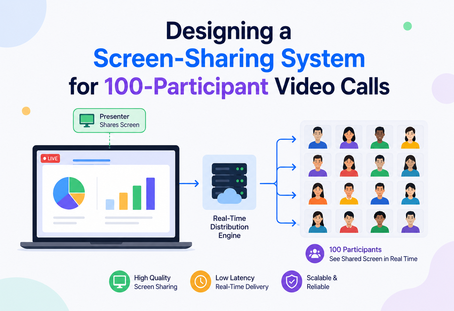
Screen Sharing for 100-Participant Video Calls
A deep, interview-ready walkthrough of how to architect real-time screen sharing that stays sharp and smooth even when a hundred people are watching at once — covering encoding, media routing, scaling, and the trade-offs real platforms like Zoom, Meet, and Teams have made.
Introduction & History
Screen sharing feels simple from the outside — you click a button, and everyone in the meeting sees your desktop. But underneath, it is one of the harder real-time media problems to solve well, especially the moment you scale a call from five people to a hundred. In this guide we design that system from scratch: a video-conferencing platform’s screen-sharing feature that must serve up to 100 concurrent viewers of a single shared screen, without the picture turning to mush or the presenter’s laptop fan spinning up like a jet engine.
Screenshot polling era
Screen sharing began with remote-desktop and web-conferencing tools like WebEx and GoToMeeting — taking periodic screenshots, compressing them as images, and pushing them to viewers every second or two. Fine for static slides, terrible for a mouse dragging a window.
Low-frame-rate video streams
Better codecs and broadband turned the screen into a 5–15 fps video stream. This is roughly where most modern platforms still sit — because screen content has long static periods, bursty motion, and fine text that regular video codecs blur.
WebRTC arrives
Standardized, royalty-free, browser-native real-time media — SRTP for transport, ICE/STUN/TURN for NAT traversal. But peer-to-peer to 99 others is a non-starter, which is why SFUs became the backbone.
SFU + simulcast/SVC + edge PoPs
Zoom, Meet, Teams, Webex, and Discord all converge on selective forwarding, layered encoding, and geographically distributed points of presence — each layer tuned for the specific statistical properties of screen content rather than reused from camera video.
Screen sharing began in the early 2000s with remote-desktop and web-conferencing tools like WebEx and GoToMeeting. Those early systems worked by taking periodic screenshots of the presenter’s screen, compressing them as images, and pushing the images to viewers every second or two. This was acceptable for static slides but terrible for anything with motion — a mouse cursor dragging a window looked like a slideshow, not a video.
The next generation, arriving with better codecs and broadband internet, treated the screen as a low-frame-rate video stream (5–15 frames per second) rather than a sequence of images. This is roughly where most modern platforms — Zoom, Google Meet, Microsoft Teams, Webex — still sit today, because screen content behaves very differently from camera video: it has long static periods (someone reading a document) punctuated by bursts of sharp motion (scrolling, video playback, or dragging a window), and it contains fine text and thin lines that regular video codecs tend to blur.
The arrival of WebRTC around 2011–2012 was the turning point for this entire industry. WebRTC gave browsers and native apps a standardized, royalty-free way to capture, encode, and transmit real-time audio and video (including screen content) directly between peers, using protocols like SRTP for encrypted transport and ICE/STUN/TURN for traversing NAT and firewalls. Screen sharing at scale, though, is not something you can do with the “peer talks directly to peer” model that WebRTC started with — sending your screen directly to 99 other people from your laptop’s upload bandwidth is a non-starter. That constraint is the entire reason media servers, and specifically the SFU (Selective Forwarding Unit) architecture, became the backbone of every serious video platform.
Today, screen sharing to 100 participants is a solved problem at companies like Zoom and Google, but it required rethinking almost every layer: capture, encoding, network transport, server-side routing, and client-side rendering all had to be redesigned around the specific statistical properties of screen content rather than camera video. That is exactly the system we will build in this guide.

One participant’s screen must be captured, compressed, and delivered to up to 99 other participants’ devices within a few hundred milliseconds, over networks of wildly different quality, on devices ranging from a high-end desktop to a mid-range phone — and it must not degrade noticeably as the audience grows from 2 to 100.
Architecture & Components
The architecture has to solve one central tension: the presenter has limited upload bandwidth (often 5–20 Mbps on a home connection), but up to 99 viewers need that same video stream, each potentially at a different quality level depending on their own network and device. Sending 99 individual streams directly from the presenter’s machine (a full mesh) would require 99× the upload bandwidth — completely impossible. So the system is built around a central relay layer.
High-Level Component Map
Capture Module
Grabs frames from the presenter’s OS-level screen or window buffer.
Encoder
Compresses captured frames using a screen-content-optimized codec profile.
Signaling Server
Coordinates session setup — who is sharing, who is viewing, negotiates codecs and network paths (SDP exchange, ICE candidates).
SFU Cluster
The heart of the system. Receives one encoded stream from the presenter and forwards it to many viewers, without decoding and re-encoding.
Simulcast / SVC Layer Manager
Produces or manages multiple quality layers of the same stream so the SFU can send the right layer to each viewer.
TURN / STUN Relay Fleet
Handles NAT traversal for clients that cannot establish a direct path to the SFU.
Media Router / Load Balancer
Assigns each call to a specific SFU node or cluster region, and can migrate sessions if a node becomes unhealthy.
Recording & Transcoding
Optional pipeline that captures the shared screen for cloud recording or for viewers on a low-bandwidth “video” fallback.
Presence & Session Store
Tracks who’s in the call, who’s sharing, participant roles, and permissions.
Client Renderer
Decodes the incoming stream and paints it to the viewer’s screen, with adaptive buffering.
Why an SFU and Not a Mesh or an MCU
There are three classic topologies for multi-party real-time media, and the choice between them is one of the most common interview questions in this space.
| Topology | How It Works | Why It Fails (or Works) at 100 Participants |
|---|---|---|
| Full Mesh (P2P) | Every client sends its stream directly to every other client. | Upload bandwidth scales linearly with participant count. At 100 viewers, the presenter would need to upload the stream 99 times simultaneously — completely infeasible on any consumer connection. |
| MCU (Multipoint Control Unit) | A central server decodes all incoming streams, composites/mixes them into a single new stream, and re-encodes it for each viewer. | Solves the bandwidth problem but shifts an enormous CPU cost onto the server (decode + composite + re-encode per viewer group), adds encode/decode latency, and locks all viewers into the same rendered layout and quality — bad for adaptive quality per viewer. |
| SFU (Selective Forwarding Unit) | The server receives the encoded stream once and simply forwards (routes) copies of it to viewers, without decoding. | Server does no heavy encode/decode work per stream, only packet routing. This is why virtually every modern platform (Zoom, Meet, Teams, Webex, Discord) uses an SFU architecture as the core building block, augmented with simulcast/SVC for per-viewer quality adaptation. |
“Why not just use an MCU since it’s simpler for the client?” — A strong answer explains that MCUs trade client-side simplicity for a huge server-side cost that does not scale: decoding and re-encoding N streams for M viewers is O(N×M) CPU work, whereas an SFU’s job is closer to O(N+M) network forwarding work, which is dramatically cheaper and lets the server handle far more concurrent sessions on the same hardware.
Why Screen Sharing Is Architecturally Different from Camera Video
It is tempting to treat “share my screen” as just another video track and reuse the camera pipeline, but screen content has different statistics that change several design decisions:
- High spatial detail, low temporal motion: Text and UI elements need sharp edges preserved; regular video codecs tuned for natural motion tend to blur text. Screen sharing typically uses a “content type: screen” hint that tells the encoder to prioritize spatial detail over frame rate.
- Bursty motion: Long static periods followed by fast scrolling or video playback inside the shared window. The encoder needs to react quickly — allocate more bits when motion appears, then drop back down.
- Resolution matters more than frame rate: Viewers generally forgive 5–15 fps for a shared screen, but they will not forgive blurry text. This is the opposite trade-off from camera video, where frame rate smoothness matters more.
- One-to-many fan-out is the common case: Camera video is usually many-to-many (everyone sees everyone), but screen share is typically one-to-many (one presenter, many viewers), which simplifies some parts of the design but makes the fan-out efficiency of the SFU even more critical.
Internal Working
Zoom in from the box diagram and each component reveals a set of deliberate choices — capture-then-skip, screen-content encoder modes, simulcast layers, an SFU decision loop per viewer, and keyframe economics tuned to bursty joins.
Capture
On the presenter’s device, the OS exposes screen or window capture APIs (for example, desktop duplication APIs on Windows, ScreenCaptureKit on macOS, or the Screen Capture API in browsers). The capture module grabs frames at a target rate, typically capped around 15–30 fps for screen content, since higher rates rarely help and only burn CPU and bandwidth. A key implementation detail: the capture module should detect “no change” frames (a static screen) and skip encoding them entirely, relying on the encoder’s inter-frame prediction rather than pushing redundant full frames.
Encoding for Screen Content
The encoder — typically H.264, VP9, or AV1 depending on platform and device support — is configured with a “screen content coding” mode when available. VP9 and AV1 in particular include explicit screen-content-coding tools (like palette mode and intra block copy) that dramatically improve compression of flat-color regions and repeated patterns common in UI content. The encoder targets a variable bitrate with a cap, and uses scene-change detection to insert a fresh keyframe when the presenter switches windows or opens a new application, since the picture has changed completely and delta-frame prediction from the old screen would be wasteful.
Simulcast and SVC: Serving 100 Viewers at Different Qualities
This is the single most important scaling mechanism in the whole system. Not all 100 viewers have the same network quality or screen size — a viewer on a phone over LTE cannot and should not receive the same bitrate as a viewer on fiber with a 4K monitor. There are two standard techniques:
Simulcast
- The presenter’s client encodes the screen share into two or three independent quality layers simultaneously (e.g., 1080p, 720p, 360p).
- All layers are sent up to the SFU; the SFU picks the right layer per viewer without transcoding.
- Broad hardware encoder support — most devices can run 2–3 parallel hardware encoders.
- Simpler to implement and deploy across a fleet of heterogeneous clients.
SVC (Scalable Video Coding)
- A single encoded stream is structured into spatial and temporal layers; lower-quality versions are extracted by dropping layers.
- More bandwidth-efficient on the sender’s upload side than simulcast — only one encode.
- More complex; historically less universal decoder and browser support.
- AV1 and VP9 support SVC natively; production systems including Zoom have adopted it for screen sharing to reduce presenter upload burden while still letting the SFU adapt per viewer.
“With 100 viewers, wouldn’t sending 3 simulcast layers still mean the SFU fans out 100 individual streams?” — Yes, and that is expected and fine: the SFU’s job is cheap packet forwarding, not encoding, so fanning out to 100 viewers even from 3 upstream layers is a routing and network I/O problem, not a compute-heavy one. The expensive part (encoding multiple qualities) only happens once, on the sender’s side, or as bounded work on the SFU if it does simulcast layer selection or lightweight transrating.
The SFU’s Per-Viewer Decision Loop
For each connected viewer, the SFU continuously runs a small control loop: it monitors the viewer’s outgoing network conditions using RTCP feedback (packet loss, jitter, estimated available bandwidth via mechanisms like transport-wide congestion control), and dynamically switches which simulcast layer (or which SVC layers) it forwards to that viewer. If a viewer’s network degrades mid-call, the SFU downgrades them to a lower layer within one or two seconds; if it recovers, it upgrades them back. This is what allows the system to serve 100 viewers with wildly different conditions from the same underlying stream without the presenter’s encoder needing to know or care about any individual viewer.

Rendering on the Viewer Side
The viewer’s client decodes the incoming layer and renders it, typically into a canvas or native video surface. Because screen content is often viewed full-screen or enlarged, viewers apply a small jitter buffer (holding a few hundred milliseconds of frames) to smooth out network variability before decoding, trading a small amount of latency for a much smoother visual experience. Viewers also commonly implement “freeze frame” handling — if packets are lost and cannot be recovered via retransmission or forward error correction in time, the client holds the last good frame rather than showing corrupted video.
Keyframes and Their Outsized Role in Screen Sharing
A keyframe (or intra-frame) encodes a complete picture on its own, without referencing any previous frame, while subsequent delta frames encode only the differences from prior frames — a far smaller amount of data. Keyframes are dramatically larger than delta frames, sometimes ten times the size or more, which is why encoders try to minimize how often they are sent. But keyframes are also unavoidable in several situations that matter a great deal for screen sharing: whenever a new viewer joins mid-share and needs somewhere to start decoding from, whenever a viewer’s client detects it has fallen too far out of sync to recover cleanly through delta frames alone, and whenever the SFU switches which simulcast layer it is forwarding to a viewer, since that new layer’s delta frames reference a different frame history than the old one. A well-tuned system batches simultaneous keyframe needs where possible (for example, if ten viewers all join within the same second, requesting one keyframe from the presenter and distributing it to all ten rather than issuing ten separate keyframe requests), since an unmanaged flood of keyframe requests during a burst of new joiners can itself create a temporary bandwidth spike right at the presenter’s upload link.
Client-Side Adaptive Rendering Decisions
The viewer’s client is not a passive recipient of whatever the server sends; it actively participates in the quality decision by telling the SFU what it actually needs. If a viewer has minimized the meeting window or switched to another application tab, most platforms detect this and request a much lower layer, or pause the video entirely, since there is no perceptual benefit to spending bandwidth on a picture nobody is looking at. Similarly, if the shared screen is rendered as a small thumbnail alongside a gallery of camera video tiles, the client requests a layer whose resolution roughly matches what will actually be displayed, rather than always defaulting to the highest available quality — a small but meaningful optimization that, multiplied across 100 viewers in a call, meaningfully reduces total egress bandwidth without any visible quality loss.
Data Flow & Lifecycle
Walking through a full lifecycle helps make the abstract architecture concrete. Here is what happens from the moment a presenter clicks “Share Screen” in a 100-person call.
Session Setup Phase
Before any media flows, the signaling server validates that the requesting user has permission to share (some meetings restrict sharing to the host), checks that no one else is already sharing (most platforms allow only one active screen share at a time per meeting, occasionally two side-by-side), and assigns the session to a specific SFU node, usually the one nearest the presenter geographically or the one already hosting the rest of that meeting’s participants.
Negotiation Phase
The presenter and the SFU exchange session descriptions (SDP) describing codecs, resolutions, and simulcast layers, and exchange ICE candidates to find the best network path — direct, or via a TURN relay if direct connectivity is blocked by NAT or firewall. This handshake typically completes within a few hundred milliseconds on healthy networks.
Steady-State Streaming Phase
This is the bulk of the session’s lifetime. The presenter continuously encodes and pushes frames; the SFU continuously forwards to each subscribed viewer at that viewer’s currently appropriate layer; each viewer continuously reports network feedback that drives the SFU’s adaptation decisions. New viewers can join mid-share (late joiners) by simply subscribing to the existing track and receiving a fresh keyframe so they can start decoding immediately, without disrupting anyone else.
Teardown Phase
When the presenter stops sharing (or disconnects), the signaling server broadcasts a “share ended” event, the SFU releases the forwarding state and buffers associated with that track, and viewers’ clients tear down their decoder pipeline for that stream. If the presenter’s connection drops unexpectedly rather than stopping cleanly, a timeout-based cleanup (typically a few seconds of no received packets) triggers the same teardown.
Advantages, Disadvantages & Trade-offs
Every design choice here comes with a companion cost. The tables and text below name the ones you will be asked to defend in interview and encounter in production.
SFU Architecture Trade-offs
| Aspect | Advantage | Disadvantage / Cost |
|---|---|---|
| Server CPU | Very low — no decode/encode per stream | Still needs enough CPU for packet processing, encryption, and congestion control at scale |
| Server bandwidth | N/A benefit | Scales linearly with number of viewers × their chosen quality layer — the real cost driver of an SFU system |
| Presenter upload | Only needs to upload once (or 2–3× for simulcast layers), not per viewer | Simulcast still costs 2–3× the bandwidth of a single stream on the sender’s side; SVC mitigates this but is more complex |
| Per-viewer adaptability | Each viewer can get a different quality suited to their network | Requires continuous monitoring and layer-switching logic, adding control-plane complexity |
| Latency | Low — no transcoding step adds delay | Still bound by network RTT and jitter buffer trade-offs |
Simulcast vs SVC Trade-off
Simulcast is simpler to implement and has broad hardware encoder support (most devices can run 2–3 parallel hardware encoders), but it wastes upload bandwidth and CPU on the sender because multiple independent encodes of the same content are produced. SVC is bandwidth-efficient and elegant, but has historically been harder to deploy broadly because not all decoders and browsers support it equally well, and encoder complexity is higher. Many production systems use simulcast as the default and layer in SVC selectively for codecs and clients that support it well, such as newer AV1-capable devices.
The Fundamental Bandwidth vs Quality vs Scale Trade-off
At the core, this system is always trading off three things against each other: visual quality (resolution, sharpness of text, frame rate), server and network cost (bandwidth to serve 100 viewers), and scale (how many simultaneous large meetings the platform can support on its infrastructure). Pushing quality up for everyone increases bandwidth cost roughly linearly with viewer count; the system’s real job is to spend that bandwidth budget intelligently — giving good quality to viewers who can use it, and gracefully degrading for those who cannot, rather than uniformly capping everyone to the lowest common denominator.
“If you had to cut cost by 30% for large-scale screen sharing, what would you sacrifice first?” — A well-reasoned answer targets frame rate before resolution (since screen content viewers tolerate 8–10 fps far better than blurry text), and considers a “large gallery” cap on the number of simultaneous highest-quality layer subscribers, tiering more distant or lower-priority viewers to a shared lower layer, since most viewers in a 100-person call are watching passively rather than pixel-inspecting the content.
Performance & Scalability
We now scale this design to a platform-wide scenario: not just one 100-person call, but a video platform running many thousands of such calls concurrently, generating millions of signaling and media-control requests per minute across its infrastructure.
The Real Scaling Bottleneck: Bandwidth, Not Compute
For SFU-based systems, the dominant scaling constraint is almost always egress bandwidth, not CPU. A single 100-person screen share, if every viewer received a 1.5 Mbps stream, requires roughly 150 Mbps of sustained egress from one SFU node for that one call. A data center hosting a few hundred such large calls concurrently needs tens of gigabits per second of sustained egress — this is why video platforms invest heavily in points of presence close to users and negotiate direct peering with ISPs, rather than relying purely on generic cloud egress.
SFU Cluster Scaling Strategy
- Horizontal SFU scaling: Each SFU node handles a bounded number of concurrent streams/viewers (a practical ceiling based on CPU for packet processing/encryption and NIC bandwidth). New calls, or large calls exceeding one node’s capacity, are distributed across a fleet using a media router that tracks each node’s current load.
- Cascading SFUs for very large meetings: For a 100-person call, some platforms cascade SFUs — the presenter’s stream is forwarded once from the origin SFU to one or more “relay” SFUs in other regions or availability zones, each of which then fans out to its local cluster of viewers. This avoids the origin SFU needing 100 direct egress connections and reduces cross-region latency for geographically distributed audiences.
- Regional Points of Presence (PoPs): Placing SFU capacity physically close to users (edge locations) minimizes RTT and reduces the chance of congestion on long-haul internet paths, which matters enormously for screen sharing since even brief congestion causes visible stutter or blur.
Congestion Control at Scale
Every viewer connection runs a congestion control algorithm (commonly Google Congestion Control, GCC, or newer approaches like BBR-inspired bandwidth estimation adapted for real-time media) that continuously estimates the safe sending rate based on observed packet loss and delay trends. At scale, the SFU must run this per-viewer estimation efficiently — typically using lightweight, event-driven feedback processing rather than per-viewer threads, so a single SFU process can manage state for thousands of viewer connections without excessive context-switching overhead.
Capacity Planning Numbers (Illustrative)
| Metric | Approximate Target |
|---|---|
| Bitrate per viewer (screen share, adaptive) | 150 Kbps (low) to 2.5 Mbps (high, e.g. 1080p sharp text) |
| Total egress for one 100-viewer call | ~30–100+ Mbps depending on quality mix |
| Concurrent large calls per SFU node (rough) | Tens, bounded by NIC bandwidth and CPU for encryption/packetization |
| Signaling requests per minute at platform scale | Millions, mostly presence updates, RTCP feedback summaries, and layer-switch decisions |
| Target end-to-end latency (glass-to-glass) | Under 300–500 ms for a good experience |
Algorithmic and Data Structure Considerations
Internally, the SFU maintains, per viewer, a small state machine tracking current subscribed layer, last keyframe request time, and jitter buffer statistics — typically stored in fast in-memory structures (hash maps keyed by viewer/track ID) rather than any database, since this state is ephemeral and must be accessed with microsecond-level latency on every packet. Layer-switch decisions use simple threshold-based or exponentially-weighted moving average (EWMA) smoothing over bandwidth estimates to avoid oscillating rapidly between layers (a phenomenon called “quality flapping” that is more visually jarring than staying at a slightly lower quality consistently).
“How would you avoid a single popular 100-person meeting overwhelming one SFU node?” — Discuss cascading SFUs, capacity-aware load balancing at session assignment time, and a fallback strategy where, if a node approaches its egress ceiling, new joiners are routed to a relay node that pulls the stream once from the origin and re-serves it locally, keeping origin egress bounded regardless of total viewer count.
Bandwidth Estimation Under Sustained Load
At platform scale, bandwidth estimation cannot be treated as a per-connection problem in isolation, because thousands of independent congestion-control loops are all sharing the same underlying network links at various points — inside a data center, across peering links, and on the last mile to each viewer. A well-designed system monitors aggregate egress utilization per network path and per SFU node, and applies admission control at the session-assignment layer: if a node’s current utilization is already close to its safe ceiling, the media router simply refuses to place a new large call there, preferring a node with more headroom even if it is a few milliseconds further away. This kind of proactive admission control prevents the far worse outcome of accepting the call and then having every viewer’s individual congestion control loop fight for scraps of bandwidth simultaneously, which produces visibly worse quality for everyone rather than a clean, predictable placement decision upfront.
Handling the “Everyone Joins at Once” Spike
A very common real-world scaling pattern is the “top of the hour” spike, where a large fraction of scheduled meetings across the platform all begin within the same few minutes. This creates a burst of signaling requests (session creation, SDP negotiation, ICE gathering) that is very different in shape from the steady-state media-forwarding load discussed earlier — it is a control-plane scaling problem, not a bandwidth problem. The signaling tier needs to be able to absorb this burst through horizontal auto-scaling of stateless signaling servers, connection-pooling to the presence store, and, where possible, pre-warming SFU capacity in each region ahead of predictable peak windows (for example, the top of business hours in major time zones) rather than reactively scaling only after load is already observed.
“Your metrics show individual SFU nodes are healthy, but new large meetings are failing to start during peak hours — what’s happening?” — This points toward the signaling or admission-control layer rather than the media-forwarding layer itself: either the signaling tier is saturated processing the burst of session-setup requests, or admission control is correctly refusing to place new large calls on nodes that look healthy in isolation but are already close to their bandwidth ceiling once the new call’s expected load is accounted for.
High Availability & Reliability
Failure Domains
The system must tolerate failures at several levels: an individual SFU process crashing, an entire data center or availability zone becoming unreachable, network partition between regions, and transient packet loss on the public internet path to any individual participant. Each has a different mitigation strategy.
SFU Node Failure and Session Migration
If an SFU node hosting an active large call fails, the platform needs a fast recovery path. Common strategies include keeping session metadata (who’s in the call, current media state) in a separate, replicated presence store rather than only in the SFU process’s memory, so a new SFU node can be spun up and clients can reconnect and resume within a few seconds, requesting a fresh keyframe to resume rendering immediately rather than waiting for the next natural keyframe interval.
Graceful Degradation Instead of Hard Failure
Reliability in real-time media is less about “never drop a packet” (impossible on the public internet) and more about graceful degradation: momentarily dropping to a lower-quality layer under congestion is far better than a full stream disconnect. The system is architected so that every viewer’s connection independently degrades or recovers, meaning one participant’s poor network never affects the other 99 viewers.
Multi-Region Redundancy
Signaling servers and media routers are deployed across multiple regions behind global load balancing (often DNS-based or anycast), so a regional outage routes new session requests to a healthy region automatically. Active calls in an affected region may need to migrate viewers to a relay SFU in a healthy region, which is why maintaining session state outside of any single SFU’s local memory is important.
Retransmission and Forward Error Correction
For screen sharing specifically, because static/text-heavy content is extremely sensitive to visible artifacts, systems commonly use a mix of Negative Acknowledgment-based retransmission (NACK, asking the sender to resend a specific lost packet) for latency-tolerant moments and Forward Error Correction (FEC, sending extra redundant data so some loss can be reconstructed without a round trip) for latency-sensitive moments, switching between them based on current round-trip time and loss rate.
Session state lives outside the SFU process
Context: Losing an SFU node during a 100-viewer live share should not kill the meeting. If all state lived in the SFU’s memory, node failure would be unrecoverable.
Decision: Presence and session metadata are kept in a replicated in-memory store; SFU processes hold only ephemeral per-connection routing state that can be rebuilt in seconds from that source of truth. New SFU nodes on failover immediately request keyframes on client reconnect.
Consequences: Slight extra memory-store bandwidth and an operational dependency on the presence tier’s reliability, in exchange for “recover a 100-viewer share within a few seconds” behavior instead of “call ends”.
“How do you keep one participant’s terrible Wi-Fi from disrupting the shared screen for everyone else?” — The key insight to voice: an SFU’s fan-out model naturally isolates each viewer’s link as an independent problem, since forwarding decisions are made per viewer, unlike a naive broadcast model where the whole distribution would be bottlenecked by the worst link.
Security
Encryption in transit
All media, including screen-share video, is encrypted end-to-end between the client and the SFU (and, in E2EE deployments, between clients themselves) using SRTP with keys established via DTLS. Signaling traffic (SDP exchange, session control messages) runs over TLS.
End-to-end encryption
Some platforms offer true E2EE for screen sharing, meaning the SFU forwards encrypted packets without ever being able to decrypt content. This is architecturally harder because the SFU still needs unencrypted access to certain packet headers to make layer-switching and routing decisions, so E2EE implementations typically encrypt only the media payload while leaving a minimal set of routing metadata visible — a careful design boundary that must be reviewed closely for information leakage.
Access control
Screen sharing is a sensitive permission — a compromised or malicious participant sharing an unintended screen (accidentally revealing private information) is a real, common incident, so the system typically supports host-controlled sharing permissions, and a visible on-screen indicator to the presenter showing exactly what is being captured, to reduce accidental oversharing.
Content watermarking
For sensitive enterprise use cases, platforms may apply per-viewer visible or invisible watermarks to the shared screen (embedding the viewer’s identity subtly in the rendered frame) so that if a viewer screenshots or records the shared content and leaks it, the source can be traced back.
DoS & abuse protection
The signaling layer and TURN relay fleet are common targets for abuse (e.g., someone attempting to flood session-join requests or exploit TURN as an open relay for unrelated traffic). Rate limiting on session creation, authenticated and time-limited TURN credentials (rather than static shared secrets), and anomaly detection on unusual traffic patterns per session are standard protections.
“Why can’t the SFU be truly zero-knowledge if it needs to make quality decisions?” — Explain the tension directly: the SFU needs some visibility (e.g., packet size, sequence numbers, simulcast layer identifiers) to route and adapt streams, so full end-to-end encryption of the entire packet is incompatible with server-side adaptive forwarding; real systems make a deliberate, documented trade-off about exactly which metadata stays visible.
Monitoring, Logging & Metrics
Client-Side Quality Metrics
Every client continuously reports Quality of Experience (QoE) metrics back to the platform: frames decoded per second, frame freeze events and their duration, resolution actually rendered, round-trip time, packet loss percentage, and jitter. These are aggregated to compute a synthetic “Mean Opinion Score” style quality index per session, which is the primary signal used both for real-time debugging and for longer-term product quality tracking.
Server-Side Metrics
- Per-SFU-node CPU, memory, and — most importantly — egress bandwidth utilization against its ceiling.
- Per-session active viewer count and current layer distribution (how many viewers on high/medium/low layer).
- Keyframe request rate (a spike often signals a scene-change storm or connection instability).
- Signaling server request latency and error rates for session setup/teardown.
- TURN relay utilization, since a spike often indicates NAT traversal issues in a particular network or region.
Real-Time Alerting
Given how latency-sensitive this system is, alerting thresholds are set tighter than typical web services — for example, alerting within seconds if a region’s average frame-freeze rate crosses a threshold, since by the time a human notices a dashboard anomaly, thousands of live meetings could already be degraded.
Distributed Tracing for Media Sessions
Each session and each viewer connection is tagged with a trace ID that flows through signaling, SFU assignment, and media forwarding logs, so that when a support ticket comes in (“my screen share was blurry for one viewer”), engineers can reconstruct exactly which SFU node handled that connection, what layer was assigned, and what the bandwidth estimation looked like at that moment.
“What single metric would you page an on-call engineer for at 3am?” — A strong answer picks something that directly reflects user-visible pain at scale, such as a sudden spike in frame-freeze rate or failed session-join rate across a region, rather than an infrastructure metric like raw CPU, since infra metrics can be healthy while users are still having a bad experience.
Deployment & Cloud Considerations
Bare Metal / Dedicated Capacity vs Generic Cloud
Because egress bandwidth is the dominant cost and constraint for SFU workloads, many large video platforms run their media-forwarding layer on a mix of dedicated data center capacity with negotiated bandwidth pricing and direct ISP peering, rather than purely on generic public cloud compute, where egress bandwidth pricing at this scale becomes very expensive. Signaling, presence, and control-plane services, which are far less bandwidth-hungry, are more commonly run on standard cloud infrastructure for elasticity.
Global Points of Presence
SFU capacity is deployed across many geographic regions so that presenters and viewers connect to the nearest healthy node, minimizing latency and keeping traffic on well-peered network paths as much as possible before it has to cross the open internet.
Auto-Scaling Characteristics
Unlike typical stateless web services, SFU nodes are not trivially auto-scalable mid-session, because an active call’s media state lives on a specific node. Scaling instead happens at the “new session assignment” layer — the media router directs new calls to nodes with spare capacity — while existing nodes are drained (stopped from accepting new sessions, but left running existing ones) before being taken down for maintenance or scale-in.
Cost Optimization
Because bandwidth dominates cost, the most effective cost levers are: aggressive but perceptually safe bitrate capping per layer, cascading to avoid duplicate cross-region transit, and encouraging viewers to receive the lowest layer that still meets a quality bar (e.g., a viewer with a small window thumbnail of the shared screen genuinely does not need the 1080p layer, so the client should request a lower layer based on its actual rendered size, not just network capacity).
Put the bandwidth-heavy media plane where bandwidth is cheap and directly peered; put the bursty control plane where compute is elastic and cheap. Trying to run both on the same substrate optimizes for neither.
“Would you deploy this entirely on public cloud?” — A nuanced answer recognizes that public cloud is excellent for the elastic, bursty control plane (signaling, presence, auth) but that the bandwidth-heavy media-forwarding layer often benefits from dedicated capacity and direct peering once you’re operating at real scale, purely on unit economics.
Databases, Caching & Load Balancing
What Actually Needs Persistent Storage
Most of this system’s hot path is deliberately stateless or ephemeral — media packets are never written to a database. What does need durable storage: user accounts and permissions, meeting metadata (scheduled time, participant list, host), and, if recording is enabled, the recorded screen-share video files themselves along with their metadata.
Presence and Session State
Live session state (who’s currently in a call, who’s currently sharing, current SFU assignment) needs to be fast to read and write but does not need long-term durability — this is a classic fit for an in-memory data store (like Redis) with replication for fault tolerance, rather than a traditional relational database, since the access pattern is high-frequency small reads/writes with a natural expiry when a session ends.
Caching Layer
Meeting configuration and permission data (does this user have rights to share their screen in this meeting?) is read very frequently but changes rarely, making it a strong candidate for aggressive caching close to the signaling servers, with cache invalidation triggered on explicit permission changes rather than relying purely on TTL expiry, since permission changes need to take effect immediately for security reasons.
Load Balancing Layers
| Layer | What It Balances | Typical Approach |
|---|---|---|
| Global entry point | Which region a user connects to | Geo-DNS or anycast routing to nearest healthy region |
| Signaling tier | Session setup requests across signaling servers | Standard stateless load balancing (round robin / least connections) |
| Media router | Which SFU node hosts a new call | Capacity-aware assignment based on current egress and CPU headroom per node |
| TURN relay fleet | NAT-traversal fallback connections | Geo-aware assignment, with load-based fallback if the nearest relay is saturated |
Recording Storage
If cloud recording of the screen share is enabled, the recorded stream is typically written to durable object storage, with a background transcoding pipeline generating a few standard playback resolutions after the fact, decoupled entirely from the live real-time path so recording load never impacts live call quality.
“Why not just store session state in a normal relational database?” — Because the access pattern (extremely high read/write frequency, short-lived data, tolerance for eventual rather than strict consistency across regions) is a much better match for an in-memory store, and putting this on a relational database would create a needless bottleneck and single point of contention for the entire platform’s live traffic.
APIs, Microservices & Protocols
Service Decomposition
The platform is naturally decomposed into a handful of focused services: an Auth/Identity service, a Meeting/Session Management service (scheduling, participant lists, permissions), a Signaling service (real-time SDP/ICE exchange, usually over WebSocket), the SFU media-forwarding fleet (a distinct, specialized service class from everything else), a Presence service, a Recording/Transcoding service, and a Notifications service (meeting reminders, “someone started sharing” events).

Protocol Choices
WebSocket
Persistent connection is preferred over plain REST for signaling, because the server needs to push real-time events (someone started/stopped sharing, a participant joined) to clients without polling.
SRTP over UDP
UDP avoids the head-of-line blocking and retransmission delays that TCP would introduce into real-time video. A TCP/TLS fallback via TURN is used for restrictive networks.
REST / gRPC
Standard REST or gRPC for meeting management, scheduling, and administrative actions where strict ordering and real-time push are not required.
Why Media Uses UDP, Not TCP
This is a foundational networking decision worth understanding deeply. TCP guarantees ordered, lossless delivery by retransmitting lost packets and blocking all subsequent data until the lost packet arrives — exactly the wrong behavior for real-time video, where a video frame from half a second ago that finally arrives is worse than useless; it’s better to simply drop it and move on to the current frame. UDP has no such guarantee, which is precisely why SRTP is built on top of it, with the application layer (not the transport layer) deciding what to do about loss — retransmit selectively via NACK, apply forward error correction, or simply accept the loss and let the decoder conceal it.
Inter-Service Communication
Within the backend, services that need to coordinate — like the Meeting Management service telling the Signaling service that a new participant was approved — typically communicate via a message bus or lightweight event system for loose coupling, while latency-sensitive control decisions (like the media router picking an SFU node) use direct low-latency RPC calls to avoid unnecessary queueing delay in the critical session-setup path.
“Why is signaling separate from the media path entirely?” — Because they have fundamentally different requirements: signaling needs reliability and ordering (you never want to lose a “stop sharing” event), which fits TCP/WebSocket well, while media needs low latency more than reliability, which fits UDP/SRTP — conflating the two into one protocol would force a bad compromise on both.
Design Patterns & Anti-Patterns
Useful Patterns
Selective Forwarding
Route encoded media without transcoding — the single most important pattern in this whole design.
Adaptive Bitrate via Layered Encoding
Produce multiple quality layers once, adapt per consumer at delivery time — directly borrowed from and analogous to adaptive bitrate streaming in on-demand video (HLS/DASH), applied to the real-time case.
Backpressure-Driven Degradation
Let downstream congestion signals (RTCP feedback) drive upstream behavior (layer selection) rather than assuming a fixed, unchanging quality.
Cascading Fan-Out
Replicate a stream once per region rather than once per viewer at the origin, reducing redundant cross-region transit — the same principle behind CDN edge caching, applied to live media.
Circuit Breaking on Node Health
The media router stops assigning new sessions to a node approaching capacity limits, isolating the problem before it affects call quality.
Anti-patterns to Avoid
Using the same encoder profile and frame-rate priorities for both ignores the very different statistical properties of screen content, leading to blurry text and wasted bandwidth.
Tempting for its simplicity in 1:1 or tiny group calls, but it fundamentally does not scale past a handful of participants and should never be extended toward 100-person calls.
Forcing everyone onto the same stream quality means either punishing good-network viewers with unnecessarily low quality, or breaking the experience for poor-network viewers — the entire point of simulcast/SVC is to avoid this false choice.
Adds unnecessary latency and creates a bottleneck for data that is inherently short-lived and doesn’t need durability.
Requesting a full keyframe too eagerly on any small hiccup wastes bandwidth (keyframes are much larger than delta frames) and can itself cause a burst of congestion — a classic “fixing it makes it worse” failure mode.
Sending a viewer a high-resolution layer when their client is displaying the shared screen in a small thumbnail wastes bandwidth for zero perceptible quality benefit.
“What’s a subtle anti-pattern that looks fine in small-scale testing but fails at 100 participants?” — A great answer is the fixed single-quality stream: it works fine when testing with 2–3 people on good office Wi-Fi, but completely falls apart once a real 100-person audience includes a wide spread of network conditions, exposing why adaptive per-viewer layering isn’t optional at scale — it’s the whole point.
Best Practices & Common Mistakes
Best Practices
- Use a screen-content-aware encoder configuration (screen content coding tools, higher spatial priority) rather than reusing camera-video encoder defaults.
- Cap frame rate for screen sharing at a sensible ceiling (commonly 15–30 fps) since higher rates rarely add perceptible value for typical screen content and only cost bandwidth.
- Always implement simulcast or SVC — never ship a real-time video product at this scale with a single fixed quality stream.
- Base layer selection on both network conditions and rendered display size on the viewer’s screen, not network alone.
- Cascade SFUs for geographically distributed large meetings to avoid a single node becoming an egress bottleneck.
- Keep session/presence state outside of any single SFU process’s memory so failures are recoverable without losing the whole call.
- Instrument client-side QoE metrics from day one — server-side metrics alone will not reveal what a real user actually experienced.
- Design keyframe request logic conservatively; prefer NACK-based recovery for small losses over full keyframe requests.
Common Mistakes
- Optimizing purely for average-case bandwidth and not testing under simulated packet loss and jitter, which is where real user complaints originate.
- Under-provisioning TURN relay capacity — in networks with restrictive firewalls (common in enterprise settings, which is exactly where a lot of screen sharing happens), a meaningful fraction of participants may need TURN relaying, and undersized TURN capacity becomes an invisible bottleneck.
- Not load-testing with a realistic mix of network conditions among the 100 viewers — testing with 100 simulated viewers all on identical, perfect network conditions hides the exact adaptive-layering problems that matter most in production.
- Forgetting that late joiners need an immediate keyframe, not the next scheduled one, or they will see a black or frozen screen for several seconds after joining.
- Coupling the recording pipeline too tightly to the live path, risking live quality degradation whenever recording processing is under load.
“What’s the first thing you’d load-test before shipping this to production?” — A thoughtful answer prioritizes heterogeneous network simulation (mixing great, mediocre, and poor simulated connections across the 100 viewers) over simply scaling up viewer count on uniform conditions, since that heterogeneity is what actually exercises the adaptive layer-selection logic that makes or breaks the real-world experience.
Real-World & Industry Examples
The design patterns above are not theoretical — they show up, tuned differently, in every major production platform. Comparing them is one of the fastest ways to see which trade-offs matter for which use cases.
SVC + screen-content encoding
Zoom’s architecture is built around its own SFU-based media routing infrastructure with global data centers and, notably, has publicly discussed adopting SVC (specifically AV1 and enhanced encoding techniques) to improve screen-sharing efficiency, letting a single upload stream serve viewers across a range of quality tiers without the overhead of full simulcast. Zoom also applies dedicated screen-content encoding optimizations, since a large share of its enterprise usage is screen sharing rather than camera video.
Backbone-assisted delivery
Google Meet runs on Google’s global network backbone, which gives it an advantage in point-to-point network quality between its media servers and users, reducing reliance on the public internet for a large portion of each connection’s path. Meet uses adaptive simulcast and dynamically adjusts screen-share quality based on both the presenter’s upload capacity and each viewer’s downlink conditions.
Cascading + webinar-scale meetings
Teams integrates screen sharing tightly with its broader Microsoft 365 and Azure infrastructure, using Azure’s global network of data centers for its media relay layer, and has invested specifically in optimizing “Together Mode” and large-meeting scenarios (Teams supports very large “webinar” style meetings) which push especially hard on the cascading-SFU and large-scale fan-out patterns discussed in this guide.
Higher-fps for gaming
Discord’s screen-sharing feature (“Go Live”) is built on its own SFU infrastructure and is a good example of a platform that had to specifically re-architect for higher frame-rate, lower-latency screen sharing to support gaming use cases, where viewers expect smoother motion than typical office-document screen sharing — illustrating how the “typical” screen-share assumptions in this guide (low frame rate is fine) don’t universally apply and must be tuned to the actual use case.
Adaptive bitrate over CDN
Though not a screen-sharing product, Netflix’s adaptive bitrate streaming over CDN edge nodes is the closest large-scale analogy to per-viewer adaptive layer selection — the same core idea (serve the highest quality a given viewer’s network can sustain, encoded once as multiple pre-computed renditions) appears in both, just applied to on-demand versus real-time delivery.
FAQ, Summary & Key Takeaways
Why can’t the presenter just send one stream and let each viewer’s client scale it down locally?
Because the bottleneck is bandwidth, not just rendering. If everyone received the same full-quality stream, viewers on constrained networks would experience severe buffering or frame drops regardless of how their client scales the picture afterward. Quality must be adapted before the data is sent over the constrained link, not after it arrives.
Does the system need a database in the real-time path at all?
No — the live media and session-state path is designed to avoid durable database writes entirely, relying on in-memory stores for session state and leaving databases for account, meeting metadata, and recorded content, which are not latency-critical.
How is this different from designing camera-video conferencing?
The transport, SFU, and scaling architecture are largely shared, but the encoder configuration, frame-rate targets, and quality priorities differ significantly because screen content has different visual statistics (sharp static detail vs. natural motion) than camera video.
What happens if the presenter’s own network is poor?
Simulcast/SVC quality is fundamentally capped by what the presenter can upload — if their upload bandwidth is low, even the highest layer they send may be modest quality, and every viewer’s best possible experience is bounded by that. This is why some platforms show the presenter a live indicator of their own upload health.
Is 100 participants meaningfully harder than 20?
The core SFU/simulcast mechanics don’t fundamentally change, but at 100 the aggregate egress bandwidth from a single node, the need for cascading across regions, and the diversity of network conditions among viewers all become significant enough that they can no longer be an afterthought — this is roughly the scale where naive single-node, single-quality designs start to visibly break down.
Summary
The whole design is a story about spending expensive bandwidth wisely. An SFU is the fan-out primitive that keeps server compute cheap; simulcast or SVC is the adaptation primitive that lets 100 different viewers each get a quality suited to their own network without punishing the sender; cascading SFUs push the same idea across regions; and ephemeral session state, UDP-based transport, and screen-content-aware encoding are all supporting choices that only make sense once you understand which resource is scarce (network) and which is not (CPU).
SFU, not mesh or MCU
The one architectural choice that makes everything else possible — cheap forwarding beats expensive transcoding at scale.
Simulcast / SVC
Layered encoding is the mechanism that lets one presenter serve 100 heterogeneous viewers gracefully.
Cascading across regions
Ship the stream once per region, not once per viewer from origin. Same principle as CDN edge caching, applied live.
UDP over TCP
Real-time media prefers dropping a late frame over waiting for it. That single fact drives most of the wire-format choices.
Key Takeaways
- An SFU (Selective Forwarding Unit) architecture, not a mesh or MCU, is the foundation for scaling one-to-many screen sharing efficiently.
- Screen content needs its own encoder tuning — prioritizing spatial sharpness over frame rate, unlike camera video.
- Simulcast and SVC are what let 100 viewers with different network conditions all get an appropriate quality from a single upstream source.
- Bandwidth, not compute, is the dominant scaling and cost constraint for real-time media at this scale.
- Cascading SFUs across regions avoids a single node becoming a bottleneck for geographically spread audiences.
- Reliability comes from per-viewer independent degradation and out-of-process session state, not from trying to eliminate all packet loss.
- UDP-based transport (SRTP) is a deliberate choice, trading guaranteed delivery for low latency, which real-time media needs far more.
- Real production systems (Zoom, Meet, Teams, Discord) all converge on these same core patterns, tuned differently for their specific use cases.
Strong candidates never say “just add more servers.” They name the scarce resource (egress bandwidth), pick a topology that respects it (SFU with cascading), and defend a specific set of trade-offs about frame rate, resolution, and per-viewer adaptation — then admit clearly what breaks first if any of those assumptions changes.