Designing Graceful Network Degradation for a Video Calling App
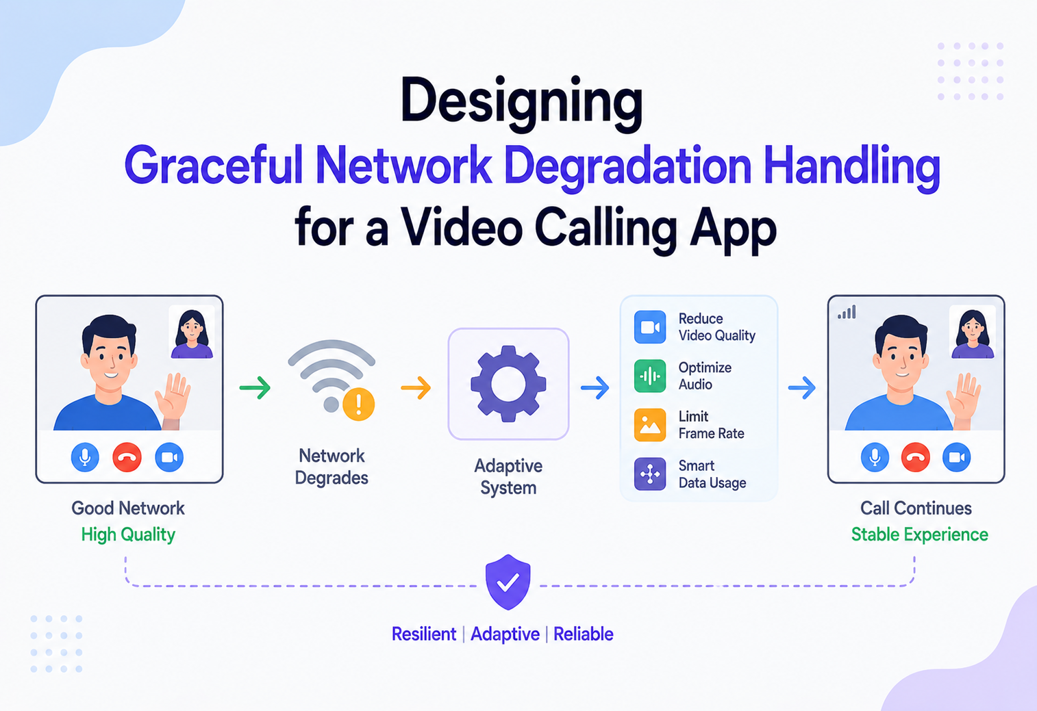
How production video platforms keep a participant “in the room” when their network gets bad — instead of dropping them — through adaptive bitrate, layered video, jitter buffering, forward error correction, and state-machine-driven reconnection.
Introduction & History
Imagine you’re on a video call with your manager, and you walk into an elevator, or your neighbor starts streaming a 4K movie on the same Wi-Fi router. Your network suddenly has less bandwidth, packets start arriving late or not at all, and your upload jitters wildly. On a badly engineered video calling system, this moment looks like a frozen frame, a robotic voice, and eventually a hard disconnect — you’re kicked out of the meeting and have to rejoin from scratch, often missing the last two minutes of a conversation.
On a well-engineered system — Zoom, Google Meet, Microsoft Teams, FaceTime, Discord — the same moment looks completely different. Your video resolution quietly drops from 720p to 360p. Your camera might turn into a still frame while your audio keeps flowing crystal clear. A small “poor connection” indicator appears near your name. Thirty seconds later, when you get off the elevator, everything snaps back to normal, and nobody in the meeting even noticed anything happened. That silent, graceful adaptation — never the abrupt goodbye — is the subject of this tutorial.
Why This Problem Exists
Real-time video is fundamentally different from a file download or a web page load. A web page can retry a failed request forever — the user just waits a little longer. Real-time audio and video have a strict deadline: a video frame that arrives 3 seconds late is worthless, because the moment it was meant to represent has already passed. This means video calling systems cannot rely on the same “just retransmit until it works” strategy that TCP uses for web traffic. They need to make a continuous stream of split-second decisions: drop this frame, lower this resolution, skip this audio packet, or wait a few more milliseconds — all while a human is speaking and expects a natural conversation.
A Brief History of the Problem
Early consumer video calling (think Skype in the mid-2000s, iChat AV, or the first-generation of Google Hangouts) treated network hiccups fairly bluntly: video would freeze, audio would cut out, and the call would frequently just drop, requiring a manual “reconnect.” Bandwidth estimation was primitive, and most systems used a single fixed-quality stream — if the network couldn’t sustain it, the whole stream suffered equally.
The turning point came with three converging developments:
WebRTC (2011 onward)
Google open-sourced a real-time communication stack with built-in congestion control, jitter buffering, and codec-level resilience, which became the substrate that most modern browser and mobile calling apps are built on.
Scalable Video Coding & Simulcast
Instead of encoding one video stream at one quality, senders began encoding multiple quality “layers” simultaneously, so a receiver (or the server relaying to them) could pick a lower layer under network stress without renegotiating the whole call.
SFU-based cloud architectures
Selective Forwarding Units (SFUs) replaced older peer-to-peer mesh and centralized transcoding (MCU) architectures, letting the server make per-participant, per-moment quality decisions instead of forcing every participant to receive the same stream.
Today, graceful degradation is considered a first-class, non-negotiable feature of any serious video calling product — arguably as important as raw video quality itself, because most real-world networks (home Wi-Fi, mobile data, hotel internet, coffee shop Wi-Fi) are imperfect for a meaningful fraction of every call.
- Why can’t video calling systems just use TCP and retransmit lost packets like a normal web request?
- What’s fundamentally different about real-time media compared to a file transfer?
- Why did the industry move from peer-to-peer mesh calling to server-mediated (SFU) architectures?
Architecture & Components
A production-grade video calling system built for graceful degradation is not one service — it’s a coordinated set of client-side and server-side subsystems that continuously negotiate quality. At a high level, three planes work together: the signaling plane (who’s in the call, session setup), the media plane (the actual audio/video packets), and the control/telemetry plane (network quality measurement and adaptation decisions).
2.1 Client-Side Capture & Adaptive Encoder
Every call starts at the device: camera and microphone capture raw frames and audio samples. The encoder is the single most important actor in graceful degradation, because it decides how much data to produce in the first place. Modern encoders (VP8, VP9, H.264, AV1) support:
- Simulcast — encoding the same video at 2–3 independent quality levels (e.g., 180p, 360p, 720p) simultaneously, each as its own RTP stream.
- Scalable Video Coding (SVC) — encoding a single bitstream with embedded spatial and temporal layers, so a receiver (or the SFU) can drop upper layers without decoding a separate stream.
- Dynamic bitrate control — continuously adjusting target bitrate, frame rate, and resolution based on feedback from the bandwidth estimator.
2.2 Bandwidth Estimator
This component runs on the sending side (and cooperatively on the receiving side) and continuously estimates how much bandwidth is actually available on the network path right now — not five seconds ago. The two dominant algorithm families are Google Congestion Control (GCC), which uses one-way delay gradients and packet loss, and Transport-wide Congestion Control (TWCC), which uses precise per-packet acknowledgment feedback from the receiver. The estimator’s output — a target send bitrate — feeds directly back into the encoder.
2.3 Selective Forwarding Unit (SFU)
The SFU is the server-side traffic cop for the media plane. Unlike a Multipoint Control Unit (MCU), which decodes and re-encodes every stream (expensive, adds latency), an SFU simply forwards the RTP packets it receives, choosing which layer of each sender’s simulcast/SVC stream to forward to each individual receiver. This is what allows Participant A (on great Wi-Fi) to receive Participant C in 720p, while Participant B (in a struggling elevator) receives Participant C in 180p — from the exact same encoded source, with zero extra encoding work.
2.4 Jitter Buffer & Packet Loss Concealment (PLC)
On the receiving side, packets rarely arrive in a perfectly even rhythm — network jitter causes them to bunch up or arrive late. The jitter buffer holds incoming packets briefly and releases them to the decoder at a steady cadence, trading a small amount of latency for a huge amount of smoothness. When packets are lost entirely, PLC synthesizes a plausible replacement (for audio, this might be a brief extrapolation of the waveform; for video, the last good frame is held or interpolated) rather than leaving a hole.
2.5 Signaling Server & Session State Store
Signaling (typically over WebSocket) coordinates call setup, participant join/leave, and — critically for this topic — ICE candidate exchange and renegotiation when a participant’s network path changes entirely (e.g., switching from Wi-Fi to cellular). Session state (who’s in the call, what quality tier each participant currently has, reconnection tokens) is generally stored in a fast, replicated store like Redis so any signaling server instance can pick up the session.
2.6 STUN/TURN Infrastructure
STUN servers help clients discover their public IP/port for direct connectivity. TURN servers act as a relay of last resort when direct peer or SFU connectivity is blocked by strict NATs or firewalls — critically, TURN is also a resilience tool: if a participant’s primary UDP path becomes unusable, the client can fail over to a TURN relay (sometimes over TCP/TLS on port 443) to keep the call alive even on hostile networks like corporate firewalls.
- Why is an SFU preferred over an MCU or a full peer-to-peer mesh for group calls?
- What’s the difference between simulcast and SVC, and when would you choose one over the other?
- Where does the bandwidth estimation logic live — client, server, or both — and why?
Internal Working
Graceful degradation is best understood as a continuous feedback control loop, not a one-time decision. Every few hundred milliseconds, the system asks: “How good is this network path right now, and what should we change in response?”
3.1 The Quality Signal Pipeline
Three raw signals feed the adaptation decision:
- Packet loss rate — derived from RTCP Receiver Reports or TWCC feedback; a rising loss rate is the clearest sign of congestion or a flaky radio link.
- Round-trip time (RTT) and jitter — measured via RTCP sender/receiver report timestamps; rising RTT variance signals queueing/buffering somewhere on the path (bufferbloat).
- Estimated available bandwidth — the output of GCC/TWCC style algorithms, which model the send-side pacing versus receive-side arrival timing to infer the bottleneck link’s capacity.
These are combined into a rolling network quality score (often normalized 0–5, similar to a cellular signal indicator), which is what actually drives both UI feedback and codec-level decisions.
3.2 The Degradation Ladder
Rather than a binary “good/bad” state, production systems implement a graduated ladder of responses, escalating only as far as necessary:
| Severity | Trigger | System response |
|---|---|---|
| Mild | Small increase in RTT/jitter, loss < 2% | Encoder trims frame rate slightly (e.g. 30fps → 24fps); jitter buffer depth increases marginally |
| Moderate | Loss 2–8%, bandwidth estimate drops 20–40% | Drop to a lower simulcast/SVC layer; reduce resolution (720p → 360p); enable FEC on audio |
| Severe | Loss > 8%, bandwidth estimate near audio-only floor | Disable video entirely, keep audio-only with aggressive redundancy (RED); show “poor connection” / avatar placeholder |
| Critical | ICE connection fails / repeated timeouts | Attempt ICE restart, fail over to TURN relay, or fail over from Wi-Fi to cellular via a parallel candidate; hold participant in a “reconnecting” state |
| Unrecoverable | No viable path after N retries within timeout window | Gracefully remove participant with a clear “connection lost” state, preserving their identity/seat so they can rejoin seamlessly |
3.3 Forward Error Correction & Redundancy
For audio in particular — where a dropout is jarring and instantly noticeable — systems commonly use FEC, sending a small amount of redundant, lower-fidelity encoding of the previous packet piggybacked on the current one. If a packet is lost, the receiver can reconstruct an approximation from the redundancy carried in the next packet, without needing a retransmission round-trip. This trades a small bandwidth overhead (5–20%) for resilience against exactly the kind of intermittent loss that mobile networks produce.
3.4 NACK and PLI (Picture Loss Indication)
For video, when a receiver detects a missing packet that’s part of a still-relevant frame, it can send a NACK (negative acknowledgment) requesting a fast, targeted retransmission — cheap because RTT is usually much shorter than the frame’s relevance window. If too much of a frame is lost to recover (e.g., a keyframe), the receiver sends a PLI, asking the encoder to produce a fresh keyframe immediately rather than waiting for the next scheduled one, which prevents prolonged visual corruption (“green screen” artifacts).
3.5 ICE Restart and Network Path Switching
Perhaps the most important internal mechanism for the “don’t drop them entirely” promise is ICE restart. When a client detects its underlying network has changed dramatically (e.g., Wi-Fi to cellular handoff, or a NAT rebinding), it can renegotiate ICE candidates over the existing signaling connection without tearing down the whole peer connection or call session. The media session’s identity is preserved; only the transport path underneath it changes.
ICE restart is analogous to changing the tires on a moving car — jarring for a moment, but the car (call) itself never stops.
3.6 Bandwidth Allocation Priority
When total available bandwidth shrinks, not all media streams are equally important, and a well-designed system allocates the shrinking budget with an explicit priority order rather than shrinking everything proportionally. A typical priority ordering, from most to least protected, looks like this:
- Audio — always protected first; this is the floor beneath which the call stops being useful at all.
- The current active speaker’s video — whoever is talking right now is what everyone is actually looking at, so their video layer is preferentially kept high even if other participants’ video is trimmed.
- Screen share content — text and UI elements in a shared screen degrade very badly with aggressive compression or resolution loss (text becomes unreadable), so screen share often gets a distinct, more conservative bitrate allocation and sometimes a slower frame rate in exchange for sharper resolution.
- Passive participants’ video (people visible in the grid but not currently speaking) — this is the first and most aggressive target for downgrade, since a small, non-speaking thumbnail tile tolerates low resolution far better than an active speaker’s face.
This prioritization is typically driven by an active speaker detection subsystem, which uses audio energy levels (and sometimes lightweight voice-activity detection) to continuously identify who is currently speaking, feeding that signal directly into the SFU’s per-subscriber layer selection logic described in Section 2.3.
3.7 Frame Rate vs. Resolution Trade-off
When an encoder must reduce its output bitrate, it has two independent levers: reduce spatial resolution (fewer pixels per frame) or reduce temporal resolution (fewer frames per second). Research and production experience both show that for talking-head video specifically, viewers tolerate a lower frame rate (e.g., 15fps) noticeably better than a blocky, low-resolution image at full frame rate — motion in a typical video call is modest, so temporal smoothness matters less than spatial clarity of the face. Because of this, most encoders are tuned to reduce frame rate before aggressively reducing resolution, reserving resolution cuts for more severe bandwidth constraints.
- Walk me through what happens, step by step, in the first 500 ms after packet loss starts climbing on a participant’s uplink.
- What’s the difference between a NACK and a PLI, and why do we need both?
- How does ICE restart avoid tearing down the whole call session?
- If total bandwidth is shrinking, how would you decide which streams to protect first — audio, active speaker video, screen share, or passive tiles?
- Why might reducing frame rate be preferable to reducing resolution for typical video call content?
Data Flow & Lifecycle
Let’s trace a concrete scenario end to end: Participant B is on a video call, walks away from their Wi-Fi router, and their connection quality drops for 45 seconds before recovering.
4.1 Detection Phase
RTCP receiver reports (or TWCC feedback packets) arrive roughly every second, carrying loss fraction, jitter, and cumulative packet counts. The SFU and the sending client both maintain a short rolling window (typically 2–5 seconds) to smooth out single noisy samples and avoid over-reacting to a single lost packet.
4.2 Decision Phase
Once the rolling quality score crosses a threshold, the system decides where to act. Critically, degradation responses are applied as close to the source of the constraint as possible: if B’s upload is constrained, B’s encoder reduces its own output layers (benefiting everyone downstream simultaneously). If a completely different participant, C, has a constrained download, only the SFU’s forwarding decision for C’s inbound streams changes — B’s encoder keeps producing 720p for everyone else who can still receive it.
4.3 Adaptation Phase
Adaptation is applied with hysteresis — the system is quick to downgrade (protect the call now) but deliberately slow and gradual to upgrade (avoid flapping back and forth, which is more jarring than staying at a slightly lower quality for a few extra seconds). A typical policy: downgrade within 1–2 seconds of sustained bad signal, but require 5–10 seconds of sustained good signal before stepping back up, and step up one layer at a time rather than jumping straight to maximum quality.
4.4 Recovery / Removal Phase
If the network path becomes entirely unusable, the client attempts ICE restart with exponential backoff (e.g., retry at 1s, 2s, 4s, 8s, capped). The session’s identity token remains valid for a grace window (commonly 30–60 seconds) so the participant can silently rejoin the exact same call state — same seat in the participant grid, same permissions — without other participants perceiving a “leave and rejoin” event, sometimes surfaced instead as a “reconnecting…” label. Only after the grace window expires does the system perform a hard removal and notify other participants that the person has left.

- Why does the system apply hysteresis — quick to downgrade, slow to upgrade?
- Where should the “who gets downgraded” decision be made when it’s a downstream (SFU) forwarding issue versus an upstream (encoder) issue?
- How would you design the grace window for a disconnected participant so it doesn’t confuse the other participants?
Advantages, Disadvantages & Trade-offs
Every knob in a graceful-degradation system comes with an explicit cost. Naming those costs up front keeps the design defensible in review.
Advantages of graceful degradation
- Perceived reliability — users experience the product as “just working” even on imperfect networks, which is a major differentiator in markets with inconsistent connectivity.
- Reduced churn from failed calls — a call that recovers automatically is far less frustrating than one that drops mid-sentence and forces a manual rejoin.
- Fairness across participants — one struggling participant doesn’t force the entire call down to the lowest common denominator, because the SFU can serve different layers to different receivers independently.
- Graceful audio-first fallback — since audio requires far less bandwidth than video, preserving audio even when video is disabled keeps the conversation itself intact, which is usually the actual purpose of the call.
Disadvantages & costs
- Engineering complexity — building and tuning a multi-signal, multi-threshold adaptation system is significantly harder than a simple fixed-quality stream and requires extensive real-world network testing.
- Server-side compute and bandwidth cost — simulcast requires the sending client to encode multiple layers simultaneously (higher CPU/battery use), and the SFU must handle more total inbound bandwidth even if it forwards less per receiver.
- Debugging difficulty — because the system reacts differently every time based on live network conditions, reproducing a specific degradation bug reported by a user is notoriously hard; extensive client-side diagnostics and telemetry become mandatory.
- UX tension — there’s a real trade-off between showing users an honest, verbose quality indicator (which can feel alarming) and hiding it (which can feel dishonest when quality clearly drops).
Key Trade-off: Latency vs. Smoothness
Every jitter buffer decision is a trade-off between end-to-end latency and playback smoothness. A larger buffer absorbs more jitter and loss but adds delay, which for a live conversation becomes awkward beyond roughly 150–200 ms one-way. Systems solve this with adaptive jitter buffers that grow during turbulence and shrink during calm periods, rather than a single fixed size.
Key Trade-off: Quality Ladder Granularity
More simulcast/SVC layers give finer-grained adaptation (smaller, less noticeable quality steps) but cost more encoding CPU and more total upstream bandwidth from the sender. Most production systems settle on 2–3 simulcast layers as the sweet spot between adaptability and resource cost.
- What’s the trade-off between jitter buffer size and perceived latency?
- Why not just always encode at the maximum number of simulcast layers for maximum flexibility?
- How would you decide whether to hide or surface network quality issues to end users?
Performance & Scalability
A video calling platform serving millions of concurrent calls has to make the entire degradation pipeline itself cheap and fast, because it runs continuously for every participant in every call, not just during incidents.
6.1 SFU Scaling Model
SFUs are typically stateless with respect to horizontal scaling at the call level — each call (or “room”) is assigned to a specific SFU instance (or small cluster of instances for very large calls), and load balancing happens at call-creation time via a signaling-layer scheduler that considers current CPU, bandwidth headroom, and geographic proximity to participants.
6.2 Cost of the Adaptation Loop Itself
Per-participant RTCP processing, quality scoring, and layer-selection decisions must run at low, predictable latency — typically the SFU re-evaluates forwarding decisions on a fixed tick (e.g., every 500 ms–1 s) rather than on every single packet, batching the work so it scales linearly with participant count rather than with raw packet rate.
6.3 Bandwidth Efficiency at Scale
Because the SFU forwards rather than transcodes, its CPU cost per participant is far lower than an MCU’s, which is what allows platforms to support calls with hundreds of participants. The bandwidth cost, however, still scales with the number of active video subscriptions — this is why large meetings typically show only a handful of active speakers’ video at a time (active-speaker detection + selective subscription) rather than every participant’s video simultaneously.
6.4 Regional TURN Relay Placement
TURN relays are deployed at edge locations close to users specifically because, when a participant fails over to TURN under network stress, the added latency of the relay hop must be minimized — a TURN relay on the wrong continent can turn a “recoverable” degraded call into an unusable one.
6.5 Synthetic Network Testing at Scale
Because degradation logic can only be validated meaningfully under actual adverse conditions, mature platforms build dedicated network emulation infrastructure into their pre-production pipeline — tools that can inject controlled packet loss, jitter, bandwidth caps, and even simulate specific real-world impairments like a subway tunnel dropout or a congested conference-hall Wi-Fi network with hundreds of competing devices. These synthetic tests run continuously in CI against every change to the encoder, bandwidth estimator, or SFU forwarding logic, catching regressions (e.g., an accidental removal of hysteresis that causes flapping) before they reach real users. Some platforms go further and run a small percentage of live production traffic through “chaos” network conditions deliberately, to continuously validate the degradation ladder end-to-end rather than relying solely on synthetic lab tests.
- How would you scale an SFU-based system to support 1,000-participant webinars?
- Why do most large meetings only render a handful of live video tiles, and how does that connect to bandwidth adaptation?
- How would you decide where to deploy TURN relay capacity geographically?
- How would you build confidence, before shipping, that your degradation logic actually behaves correctly under real-world adverse network conditions?
High Availability & Reliability
Reliability here is not just “servers stay up” — it is designed on the assumption that networks and individual media nodes will fail regularly, and the platform must absorb those failures without ejecting a live conversation.
7.1 SFU Failure Isolation
If an SFU instance crashes mid-call, the blast radius should be limited to the calls it was hosting, not the whole platform. Production systems achieve this by keeping SFU instances stateless beyond the active call’s media state, storing durable session/participant metadata in an external store (e.g., Redis), and having the signaling layer detect an SFU heartbeat failure and trigger a fast call migration — clients are told to reconnect to a freshly assigned healthy SFU with their existing session tokens, minimizing perceived disruption to a brief reconnect rather than a lost call.
7.2 Redundant Signaling Paths
The signaling layer itself is horizontally scaled and typically fronted by a WebSocket-aware load balancer with sticky routing plus a fast failover path; because signaling state (who’s connected, current ICE candidates) is externalized to a shared store, a signaling node failure doesn’t need to end active media sessions — clients simply reconnect their signaling channel and resume.

7.3 Multi-Path Connectivity
Advanced clients (especially mobile apps) probe multiple network interfaces simultaneously — Wi-Fi and cellular — and can maintain warm ICE candidates on both, so a hard failure on one interface can fail over to the other in well under a second, rather than starting network discovery from zero.
7.4 Graceful Degradation as a Reliability Primitive
It’s worth stating directly: everything in this tutorial is the reliability strategy. Rather than treating “the network got worse” as an exceptional failure to recover from, the system treats varying network quality as the normal operating condition and is built to run continuously inside that range — this reframing is why modern video platforms achieve much higher perceived uptime than older systems that treated any degradation as an error state.
- What happens to the 50 participants on a call if the SFU hosting that call crashes?
- How would you design seamless failover between Wi-Fi and cellular on a mobile client mid-call?
- How do you keep signaling servers stateless enough to fail over without dropping calls?
Security
Security in a real-time media pipeline has to protect confidentiality, integrity, and availability without ever adding perceptible latency to the conversation itself.
Encrypted media in transit
All RTP media is encrypted end-to-end over the transport using SRTP (Secure RTP), with keys negotiated via DTLS during connection setup. Encryption adds a small, fixed overhead that must be accounted for in bandwidth estimation, and ICE restarts must re-establish DTLS state securely without weakening the session.
Relay trust boundaries
Since TURN servers relay encrypted media (they cannot see plaintext content, only encrypted packets, given SRTP), they don’t introduce a confidentiality risk — but they are a valuable target for denial-of-service and abuse, so TURN credentials are typically short-lived, time-boxed tokens issued per session rather than static shared secrets.
Session token security
The reconnection/grace-window mechanism is itself a security-sensitive surface: the session token that lets a disconnected participant silently rejoin must be unguessable, scoped to that specific call and participant identity, and time-bound to the grace window — otherwise it becomes a vector for hijacking a departed participant’s seat.
Protecting adaptation inputs
RTCP feedback and TWCC reports are inputs to server-side decisions, so a malicious participant could theoretically forge quality reports to manipulate SFU forwarding behavior. Production systems apply sanity bounds and cross-validation (comparing self-reported client feedback against server-observed packet arrival patterns) rather than trusting client-reported metrics unconditionally.
- Why is SRTP + DTLS the standard for securing media, and how does it interact with ICE restarts?
- How would you design TURN credentialing to prevent relay abuse?
- What could go wrong if you trusted client-reported network quality metrics without validation?
Monitoring, Logging & Metrics
Because degradation events are, by definition, intermittent and network-dependent, thorough telemetry is what separates a system that can degrade gracefully in a lab from one that reliably does so for millions of real users on real networks.
9.1 Client-Side Metrics (via WebRTC getStats API and equivalents)
- Packet loss percentage (inbound and outbound, per stream)
- Jitter buffer delay and target delay
- Current send/receive bitrate and resolution/frame rate per active layer
- RTT and estimated available bandwidth over time
- ICE connection state transitions and restart counts
- Freeze count and freeze duration (how often and how long video visibly froze)
9.2 Server-Side Metrics
- Per-SFU CPU, memory, and total forwarded bandwidth
- Layer-switch frequency per participant (a proxy for network instability and for whether hysteresis tuning is too aggressive or too lax)
- TURN relay fallback rate — what fraction of sessions require relay vs. direct connectivity
- Call migration and SFU failover events
- Reconnection success rate within the grace window vs. hard drops
9.3 Aggregate Quality Dashboards
Beyond raw metrics, teams build a composite Mean Opinion Score (MOS) estimate — a well-established 1–5 scale approximating subjective audio/video quality, computed from loss, jitter, and delay using models like E-model for audio. Tracking MOS distribution across the entire user base over time is typically the single most important dashboard for a video calling product team, because it correlates strongly with user satisfaction and churn.
9.4 Alerting Strategy
Alerts are tiered: infrastructure-level alerts (SFU cluster CPU, TURN relay saturation) page on-call engineers immediately; product-level quality regressions (e.g., median MOS drops 10% region-wide) trigger investigation but not necessarily a page, since they may reflect genuine external network conditions (e.g., a regional ISP outage) rather than a platform bug.
- What metrics would you track to know whether your degradation-handling system is actually working well in production?
- How would you build a single quality score (like MOS) from raw network telemetry?
- How do you distinguish “our system has a bug” from “the user’s ISP is having a bad day” in your dashboards?
Deployment & Cloud
Media infrastructure has a different deployment shape from a typical stateless web service: pods hold live UDP media, calls survive rolling changes, and even canary rollouts have to be treated as user-facing quality experiments.
10.1 Global Points of Presence
Media infrastructure (SFUs, TURN relays) is deployed across many geographically distributed points of presence (PoPs), because RTT to the nearest media server directly bounds the achievable call quality — no amount of clever adaptation logic compensates for routing media across an ocean when a nearby PoP exists.
10.2 Container Orchestration Considerations
SFU processes are commonly deployed via container orchestration (e.g., Kubernetes), but with important caveats versus typical stateless web services: SFU pods hold live UDP media state for the duration of a call, so rolling deployments must use connection-draining strategies (let existing calls finish or migrate before terminating a pod) rather than abrupt pod termination, and autoscaling must consider active call count and bandwidth, not just CPU.
10.3 Blue/Green and Canary for Media Servers
Because a bad SFU deploy directly degrades live human conversations, media-serving infrastructure typically uses conservative canary rollouts — routing a small percentage of new call assignments to updated SFU versions and closely monitoring quality metrics (Section 9) before wider rollout, rather than deploying the whole fleet at once.
10.4 CDN and Edge Considerations
While the live media path is not CDN-cacheable in the traditional sense, adjacent assets (client SDKs, signaling bootstrap configuration, TURN server discovery lists) benefit from CDN distribution to minimize call setup latency, which matters especially during reconnection scenarios where every millisecond of setup delay compounds the disruption.
Context
SFU pods hold live UDP media state for the duration of every call they host. Terminating a pod abruptly (typical for stateless web services) ends every hosted call instantly, which is user-visible as a hard disconnect for potentially hundreds of participants at once.
Decision
Every SFU deployment uses connection draining: on rollout or scale-down, the pod is marked as “not accepting new calls” but continues to serve its existing calls until they end or until a hard timeout (e.g., 30 minutes). New calls are routed to freshly updated pods. Emergency terminations must trigger the call migration path (Section 7.1) rather than a raw kill.
Consequences
Slightly slower rollouts and higher pod-count during transition periods, in exchange for eliminating a class of avoidable user-visible disconnects during routine deployments.

- Why can’t you just treat SFU pods like any other stateless microservice during a rolling deployment?
- How would you canary-test a change to your congestion control algorithm safely?
- Why does PoP geography matter more for this system than for a typical web API?
Databases, Caching & State
Video calling systems are unusual in that the “hot path” (media) never touches a traditional database — but the surrounding state management is still critical, especially for the reconnection guarantees this tutorial focuses on.
11.1 Session State in Redis
Active call and participant state — who’s in the call, current quality tier, ICE candidate sets, reconnection tokens and their expiry — lives in a low-latency, replicated in-memory store such as Redis. This needs to support fast reads/writes from any signaling node (for horizontal scalability and failover) and TTL-based expiry (for automatically cleaning up grace-window tokens once they expire).
11.2 Durable Call Metadata
Longer-lived, less latency-sensitive data — call history, participant lists for compliance/recording purposes, scheduled meeting metadata — is stored in a traditional relational or document database, decoupled entirely from the real-time media path so that a database slowdown never affects live call quality.
11.3 Caching Network/Geo Data
Geo-IP lookups and “nearest PoP” resolution used during the initial SFU assignment and during ICE restart fallback decisions are cached aggressively at the edge, since recomputing them on every reconnection attempt would add unnecessary latency exactly when the system needs to be fastest.
11.4 Why No Database in the Media Hot Path
A defining architectural principle: the adaptation loop (Sections 3–4) never performs a database read or write as part of its per-packet or per-tick decision-making. All the signals it needs (RTCP reports, bandwidth estimates) are computed and consumed in-memory within the SFU/client process. This is what allows the loop to run at the sub-second latencies real-time media requires.
- Why is Redis a better fit than a relational database for live call session state?
- What data would you make durable (survive a restart) versus purely ephemeral for a call session?
- Why should the real-time adaptation loop never touch a database directly?
APIs & Microservices
The control plane is a conventional set of services with clean API contracts; the media plane is a continuous UDP stream governed by RTP/RTCP semantics. Both matter, but they must be reasoned about with very different principles.
12.1 Service Decomposition
Signaling Service
Handles join/leave, offer/answer exchange, ICE candidate relay, and renegotiation events. Stateless behind a shared session store.
Call Scheduler / Admission
Decides which SFU cluster a new call or participant should be assigned to, based on geography and current load.
SFU Fleet
The media-forwarding workhorses described throughout this tutorial; typically not a “microservice” in the REST sense, but a specialized, stateful media process fleet.
TURN / STUN Service
Connectivity and relay infrastructure, often using standard open implementations (e.g., coturn) deployed at edge PoPs.
Telemetry Ingestion Service
Receives client-reported and server-reported quality metrics and feeds monitoring/analytics pipelines.
Recording / Transcription Service
Consumes media independently of the live degradation path, so recording quality issues never affect live call adaptation.
12.2 Why the Media Path Isn’t “Just an API”
A crucial interview-relevant distinction: signaling and control-plane services are conventional request/response or event-driven microservices, reachable via REST or WebSocket APIs with normal service-to-service contracts. The media plane is fundamentally different — it’s a continuous UDP (or fallback TCP/TLS) stream governed by RTP/RTCP protocol semantics, not a request/response API, and it must be designed and reasoned about with real-time systems principles rather than typical microservice patterns like retries-with-backoff, which are actively harmful for time-sensitive media.
12.3 Renegotiation as an API Pattern
ICE restarts and layer changes are exposed to the rest of the system as signaling-plane events/messages (e.g., a WebSocket message carrying updated SDP or ICE candidates), giving the rest of the architecture a clean, well-defined API surface for what is, underneath, a highly dynamic real-time adaptation process.
- Why shouldn’t you apply typical REST API retry-with-backoff patterns to the media path?
- How would you decompose this system into services, and what are the latency-sensitivity differences between them?
- How is a renegotiation (ICE restart / layer switch) represented as a message on the signaling channel?
Design Patterns & Anti-Patterns
The design leans on a small set of well-worn patterns from real-time systems — and pointedly avoids a handful of anti-patterns that convert a recoverable network hiccup into a hard user-visible failure.
13.1 Patterns That Work
Measure → decide → adjust
Continuously measure, decide, and adjust, rather than making a one-time quality decision at call start.
Response ladder, not a switch
Multiple discrete severity tiers rather than a binary healthy/unhealthy state, so the system’s reaction is proportional to the actual problem.
Fast down, slow up
Asymmetric thresholds for downgrading (fast) versus upgrading (slow), preventing oscillation (“flapping”).
Reduced-but-functional over failed
Always prefer a reduced-but-functional state (audio-only) over a total failure (dropped call) whenever technically possible.
Decouple from transport
Preserve session identity across transport changes so ICE restarts and TURN failover don’t require rejoining.
Fix at the constraint
Apply encoder-side changes for upload constraints and SFU forwarding changes for download constraints, rather than a single blunt global quality setting.
13.2 Anti-Patterns to Avoid
Treating any packet loss as “call is broken” leads to unnecessary, jarring disconnects on perfectly recoverable networks.
Forcing every participant in a call down to the worst participant’s quality (an anti-pattern common in old MCU/mesh systems) wastes good connections unnecessarily.
Reacting instantly to every fluctuation causes rapid resolution/frame-rate oscillation, which is often more distracting than staying at a stable lower quality.
A security and correctness anti-pattern; always cross-validate against server-observed data (Section 8.4).
Discarding session/seat state on any disconnect, forcing users to fully re-enter meeting IDs/passwords for a two-second Wi-Fi hiccup, is a major avoidable UX regression.
Video is more visually obvious, but audio continuity matters more to actual conversational usability; systems that sacrifice audio stability to preserve video resolution get this backwards.
- What’s “flapping” in this context, and how do you prevent it?
- Why is audio-first degradation usually the right default over video-first?
- Can you describe an anti-pattern you’ve seen (or can imagine) in a poorly designed real-time adaptation system?
Best Practices & Common Mistakes
A distilled operational checklist for teams building or operating this kind of system — and the mistakes that most reliably show up in post-mortems.

Best practices
- Test against real degraded networks, not just simulated conditions — use network condition emulation (packet loss, latency, jitter injection, bandwidth throttling) as a mandatory part of CI/QA, covering Wi-Fi-to-cellular handoff scenarios explicitly.
- Make quality adaptation observable to users in a calm, non-alarming way — a small, quiet indicator (“Poor connection”) is usually better UX than aggressive pop-up warnings.
- Design the grace window deliberately — too short and users get dropped unnecessarily on brief hiccups; too long and “ghost” disconnected participants linger awkwardly in the call roster.
- Prioritize audio path stability above all else — allocate bandwidth headroom to guarantee audio can always survive even the most severe degradation.
- Instrument everything, and correlate client + server telemetry — the most subtle degradation bugs only show up when comparing what the client experienced against what the server observed.
- Version and gradually roll out changes to congestion-control tuning — small parameter changes can have outsized, hard-to-predict effects on real-world call quality across millions of diverse networks.
Common mistakes
- Tuning thresholds only against lab/office networks — real-world conditions (crowded mobile cells, satellite internet, developing-market broadband) are far messier and expose edge cases lab testing misses.
- Forgetting to bound retry/backoff — an ICE restart loop without a sane cap can leave a client silently retrying forever, appearing “frozen” from the user’s perspective, rather than surfacing a clear failure state.
- Coupling recording/transcription pipelines to the live adaptation path — this can make a recording-service slowdown incorrectly affect live call quality decisions.
- Underestimating mobile battery/CPU cost of simulcast — encoding 2–3 simultaneous layers is real work; on lower-end devices this can itself cause thermal throttling that ironically worsens the very quality it’s meant to protect.
- Not load-testing the SFU migration/failover path — teams often thoroughly test steady-state SFU performance but under-test what actually happens to hundreds of live calls when an SFU instance is killed.
- How would you test this system’s behavior under realistic network degradation before shipping?
- What’s a subtle production bug you could imagine occurring in a system like this, and how would you catch it?
- How would you tune the grace window for disconnected participants, and what factors would inform that number?
Real-World Industry Examples
Publicly-discussed practices from major video calling providers that map, at a high level, to the ideas in this document.
Aggressive low-bandwidth resilience
Zoom’s architecture is built around a globally distributed cloud of media servers functioning as SFU-style routers, with proprietary congestion control tuned aggressively for low-bandwidth resilience — a well-known aspect of Zoom’s early growth was its ability to maintain usable video calls on markedly worse networks (2G/3G mobile, weak Wi-Fi) than many competitors of that era, largely attributed to aggressive adaptive bitrate and a strong audio-first fallback strategy.
WebRTC + AV1 with SVC
Google Meet leans heavily on WebRTC (which Google itself originated and open-sourced) and has invested significantly in modern codecs like AV1 with SVC support, allowing more granular, lower-overhead layer adaptation than older simulcast-only approaches, particularly benefiting large-scale multi-participant calls inside Google’s global network backbone.
Enterprise-network path selection
Teams integrates deeply with Microsoft’s global Azure network backbone and Media Processors, using SFU-based relaying combined with sophisticated network path selection (including split-path routing where audio and video can, in some cases, be prioritized and routed differently based on real-time quality signals) to preserve meeting continuity across enterprise network conditions.
Voice-first, aggressive FEC
Discord, operating at massive scale for voice-first communities, is well known for prioritizing extremely low-latency, resilient audio (their custom-tuned Opus-based pipeline with aggressive FEC and jitter buffering) even before considering video, reflecting the audio-first degradation philosophy — video quality flexes considerably more than voice quality in their system by design.
Adaptation as a platform primitive
Open-source and commercial real-time infrastructure providers like LiveKit and Twilio Video expose much of this adaptation machinery (simulcast, SVC, adaptive jitter buffering, TURN failover) as configurable primitives for other companies to build calling products on top of, illustrating that graceful degradation has become a standardized, expected layer of the real-time communication stack.
The specific architectural claims above reflect general, publicly-discussed industry patterns rather than verified citations to a specific paper or blog post — please independently verify any detail before relying on it for a specific claim.
- Why has Discord historically prioritized voice resilience over video resilience in its architecture?
- How might AV1 with built-in SVC change the trade-offs compared to older VP8/H.264 simulcast approaches?
- Why would a company choose to build on a platform like LiveKit or Twilio rather than build this adaptation machinery in-house?
Frequently Asked Questions
Questions that repeatedly come up when engineers first encounter this design, answered directly.
Why not just always request a retransmission when a packet is lost, like TCP does?
A retransmission takes at least one round-trip time to arrive, and by the time it does, the moment that video frame or audio sample represented has already passed for a live conversation. Real-time media prioritizes timeliness over completeness — it’s better to conceal or skip a lost packet than to pause the whole stream waiting for it, except for a narrow set of cases (like NACK for a still-relevant recent frame) where the retransmission can plausibly still arrive in time.
What’s the actual difference between simulcast and SVC in practice?
Simulcast sends 2–3 fully independent encoded streams at different qualities, which is simple to implement and forward but uses more total sender-side encoding CPU and bandwidth. SVC encodes one bitstream with embedded layers that can be trimmed by dropping upper-layer data, which is more bandwidth-efficient but requires codec and browser support that’s historically been less universal than simulcast (though this gap has narrowed significantly with AV1 and newer VP9 deployments).
How does the system decide whether to disable video before disabling audio, or vice versa?
Audio requires drastically less bandwidth than video (tens of kbps versus hundreds of kbps to megabits) and is generally the primary carrier of conversational meaning, so nearly all production systems degrade video first and treat audio-only as the last line of defense before a full disconnect, rather than the other way around.
What actually happens on the other participants’ screens when someone degrades?
Typically a small, calm quality indicator appears near that participant’s name or video tile, their video tile may show a lower resolution (often imperceptible at typical tile sizes) or freeze on the last good frame if video is disabled entirely, while their audio — if still viable — continues uninterrupted; other participants’ own quality and layout are not forced to change.
How long does a system typically wait before removing a disconnected participant?
This varies by product, but a common range is 30–60 seconds of grace window with active reconnection attempts (using exponential backoff) before a hard removal, balancing the goal of surviving brief network blips against not leaving a confusingly “ghosted” participant in the call roster indefinitely.
Does this system design change much between a 1:1 call and a 500-person webinar?
The core adaptation mechanisms (bandwidth estimation, layered encoding, jitter buffering) stay conceptually the same, but at large scale, additional mechanisms like active-speaker-based selective subscription and stricter tiered forwarding become essential, because it’s neither bandwidth-efficient nor useful for every one of 500 participants to receive every other participant’s video simultaneously.
Why does frame rate get reduced before resolution in most encoder adaptation strategies?
For typical talking-head video content, viewers are noticeably more sensitive to blocky, low-resolution faces than to a somewhat choppier frame rate, since motion in a video call is relatively modest compared to, say, sports footage. Encoders exploit this by trimming frame rate first and reserving resolution cuts for more severe bandwidth shortfalls, which tends to produce a better subjective experience for the same bitrate budget.
Can a participant’s poor network quality affect other participants who have great connections?
In a well-designed SFU-based system, no — because the SFU makes independent per-subscriber forwarding decisions, a struggling participant’s inbound stream to the SFU is downgraded without touching what other participants send or receive. The one exception is the struggling participant’s own outbound video, which every other participant will see at a lower quality, since it’s genuinely constrained at the source by that person’s own uplink.
Summary & Key Takeaways
Zoomed back out, the entire design is a bet on discipline: measure what you can, respond in proportion, and never let a temporary network dip become a permanent user-facing failure.
Continuous feedback loop
Graceful network degradation handling is a continuous feedback loop — measure network quality, respond proportionally along a graduated ladder, and always prefer a reduced-but-functional state over a hard disconnect.
Layered encoding + SFU + ICE restart
Adaptive encoder (simulcast/SVC), bandwidth estimator (GCC/TWCC), SFU with per-subscriber layer selection, jitter buffer with PLC, FEC/NACK/PLI for loss recovery, and ICE restart for path failover.
Localize the fix to the constraint
Upstream issues are fixed at the sender’s encoder, downstream issues at the SFU’s forwarding decision per receiver — never force a global lowest-common-denominator quality.
Imperfect networks are normal
Treat imperfect networks as the normal operating condition, not an exception. Session identity is decoupled from the underlying transport path, enabling silent reconnection within a grace window rather than a full call restart.
Key takeaways
- Measure, decide, adapt — continuously. The system is a control loop, not a one-time setup decision at call start.
- Graduated ladder, not a switch. Escalate exactly as far as the network problem demands, and reverse gradually with hysteresis.
- Audio is the floor. Preserve audio at all costs; video is what flexes to absorb bandwidth loss.
- Localize the fix. Upload constraints are solved at the encoder; download constraints at the SFU; global quality lock-step is an anti-pattern.
- Session identity outlives the transport. ICE restart, TURN fallback, and reconnection tokens exist to keep the logical call alive when the physical path changes.
- Test under real adversity. Synthetic network emulation and chaos testing on live traffic are how these systems stay honest as they evolve.
Building this system well requires thinking simultaneously at multiple layers: codec-level engineering (layered video, FEC), transport-level protocol design (RTP/RTCP, ICE, DTLS/SRTP), distributed-systems architecture (stateless SFU scaling, session state externalization, failover), and product/UX judgment (how to surface degradation to users without alarming them). The unifying theme across every layer is the same: a resilient real-time system doesn’t try to eliminate network problems — it’s designed to absorb them gracefully, in proportion to their severity, while preserving the one thing that actually matters to the user: staying connected to the conversation.
If asked to design this system from a blank page, anchor your answer on the feedback loop (measure → decide → adapt), the graduated response ladder, and the principle of decoupling call/session identity from the underlying network transport — these three ideas cover the vast majority of what interviewers are probing for in this class of system design question.